5
Run-in time
6
Position in the sequence of the sampling point program
NOTICE
The green arrow (load all parameters) must be pressed after making changes in order
to see the effect of the changes for both measuring points. This then updates the data
in the Table accordingly.
Figure 77: Load parameters - button
6.5 Data interfaces / IO
Menu: Parameterization/I/O
This menu displays the data interfaces.
Hardware Plan
Menu: Parameterization/I/O/Hardware plan
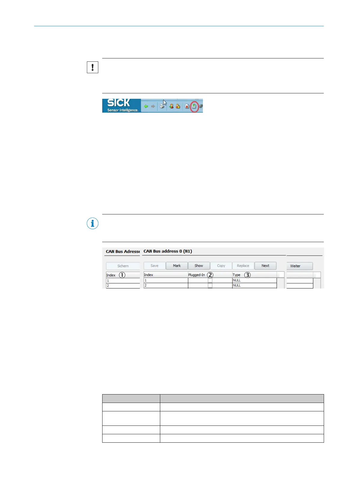
CAN bus address x
Displays the I/O modules present in the selected CAN bus gateway.
NOTE
The sequence of the specified modules must match the sequence of the plugged in
modules (starting at the gateway).
Figure 78: Menu CAN Bus address
1
Consecutive number of module.
2
Checkmark: Module is plugged in.
3
I/O module type.
Data
Menu: Parameterization/I/O/Data
6.5.1 Digital inputs
Menu: Parameterization/I/O/Data/External data/Digital inputs
This menu displays the digital inputs.
Table 7: Digital inputs
Name Remark
Index Consecutive number of the digital input (DI1, DI2, ....).
Module Topographic addressing (see "Data interfaces / IO", page 55). Generated auto‐
matically.
Name Set fixed.
Inverted Checkmark: Read in inverted.
PARAMETERIZATION 6
8017585/YXD9/V3-1/2017-05 | SICK T E C H N I C A L I N F O R M A T I O N | MARSIC300
55
Subject to change without notice