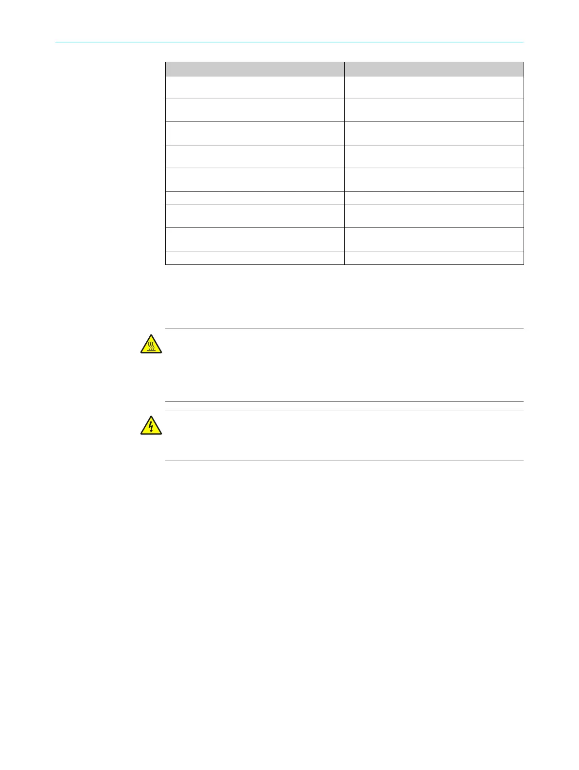
System component Reference
Connect sample gas line to analyzer see "Connect the sample gas line to the analyzer",
page 14
Connect tube bundle cable to analyzer see "Connecting the tube bundle cable to the ana‐
lyzer", page 16
Connect signal lines to analyzer see "Connecting the signal lines to the analyzer",
page 19
Air and gas connections on analyzer see "Air and gas connections on analyzer",
page 20
Electrical connections on analyzer see "Electrical connections on the analyzer",
page 23
Install SFU gas sampling system see "Installing the gas sampling system", page 25
Optional: Configure Modbus-Profinet /Profibus con‐
verter
see "Setting up the Modbus-Profinet converter
(optional)", page 27
Optional: Install measuring point switchover HOT‐
SAMPLER
See Operating Instructions HOTSAMPLER
Optional: Install MPR See Operating Instructions MPR
2.7 Assembly information for sample gas lines and tube bundle cable
Installing the sample gas lines
WARNING
Risk of fire
b
Observe the laying instructions provided with the line.
b
Minimum clearance to other lines (for example, tube bundle cable): 10 cm.
b
Do not lay or roll up lines directly next to each other.
WARNING
Danger to life by electric voltage
b
Only allow an authorized electrician to work on the electric system
b
Start laying at the analyzer.
°
The end with the electric connection belongs on the analyzer.
Important: The screw fitting for the enclosure duct must be located at the
end of the electrical connection (analyzer side).
°
The end without electrical connection belongs on the gas sampling system.
Roll-up excess length on the gas sampling system.
Leave enough length for pulling the gas sampling system.
b
Protect the line from damage (chafing through vibration, mechanical load).
b
Observe minimum bend radius of 300 mm.
Installing the tube bundle cable
Start laying the tube bundle cable at the analyzer and roll-up excess length at the gas
sampling probe.
1. Assembly on the analyzer: see "Air and gas connections on analyzer", page 20
and see "Electrical connections on the analyzer", page 23.
2. Lay the tube bundle cable to the analyzer cabinet.
°
Attach excess length to the gas sampling probe.
°
Leave enough length for pulling the probe.
°
Protect the line from damage (chafing through vibration, mechanical load).
°
Minimum bend radius: 300 mm.
INSTALLATION 2
8017585/YXD9/V3-1/2017-05 | SICK T E C H N I C A L I N F O R M A T I O N | MARSIC300
11
Subject to change without notice

 Loading...


