6. Connect the Pt100 of the gas sampling system (heated sample gas filter and
optional heated probe tube).
NOTICE
The connections on MARSIC300 must match the connections of the gas sampling
system.
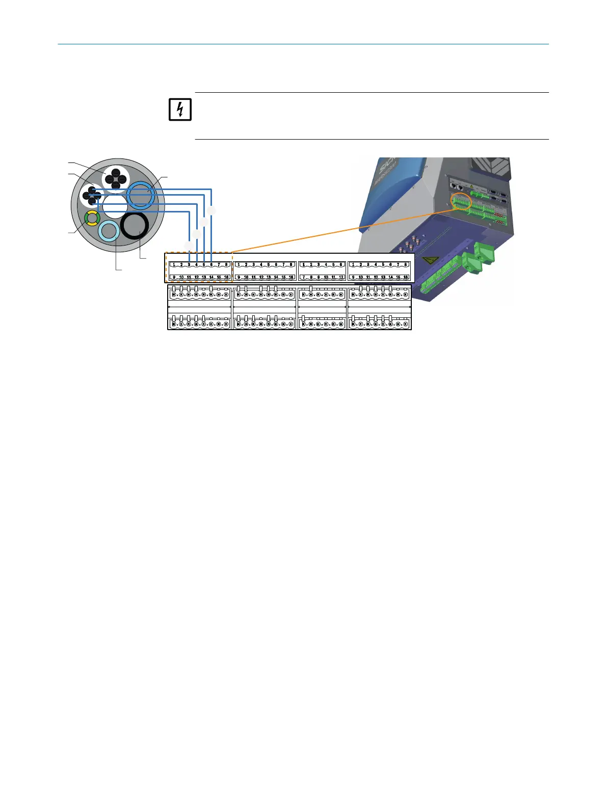
1
4
2
3
6
5
PT100 DIGITAL INPUTS DIGITAL OUTPUTS VALVE OUTPUTS
!
$
§
"
Figure 15: Signal lines - tube bundle cable connection diagram
2.11 Connecting the signal lines to the analyzer
4 digital inputs and outputs each are available as an option that must then be config‐
ured, see "Data interfaces / IO", page 55.
4 digital inputs
•
Fill level signal, condensate container
•
Condition, instrument air
•
Scrubber system on/off (can be linked with StBy MARSIC300)
•
Temperature error, weatherproof cover or other external alarm
4 digital outputs
•
Status (OK / Maintenance)
•
Status (OK / Failure)
•
Coefficient SO
2
/CO
2
less than/greater than xy (definable)
The inputs and outputs are deactivated as standard. The inputs and outputs can be
activated and negated in SOPAS ET.
Digital inputs and outputs can also be redefined differently to the above description.
INSTALLATION 2
8017585/YXD9/V3-1/2017-05 | SICK T E C H N I C A L I N F O R M A T I O N | MARSIC300
19
Subject to change without notice