•
Fixing accessories for heated sample gas line and tube bundle cable
•
Power cable: see "Power supply", page 82
•
External power disconnection unit
•
Compressed air, instrument air as zero gas when necessary
Observe quality of operator's instrument air: see "Supply gases", page 87
•
Optional span gases
2.5 Installation overview
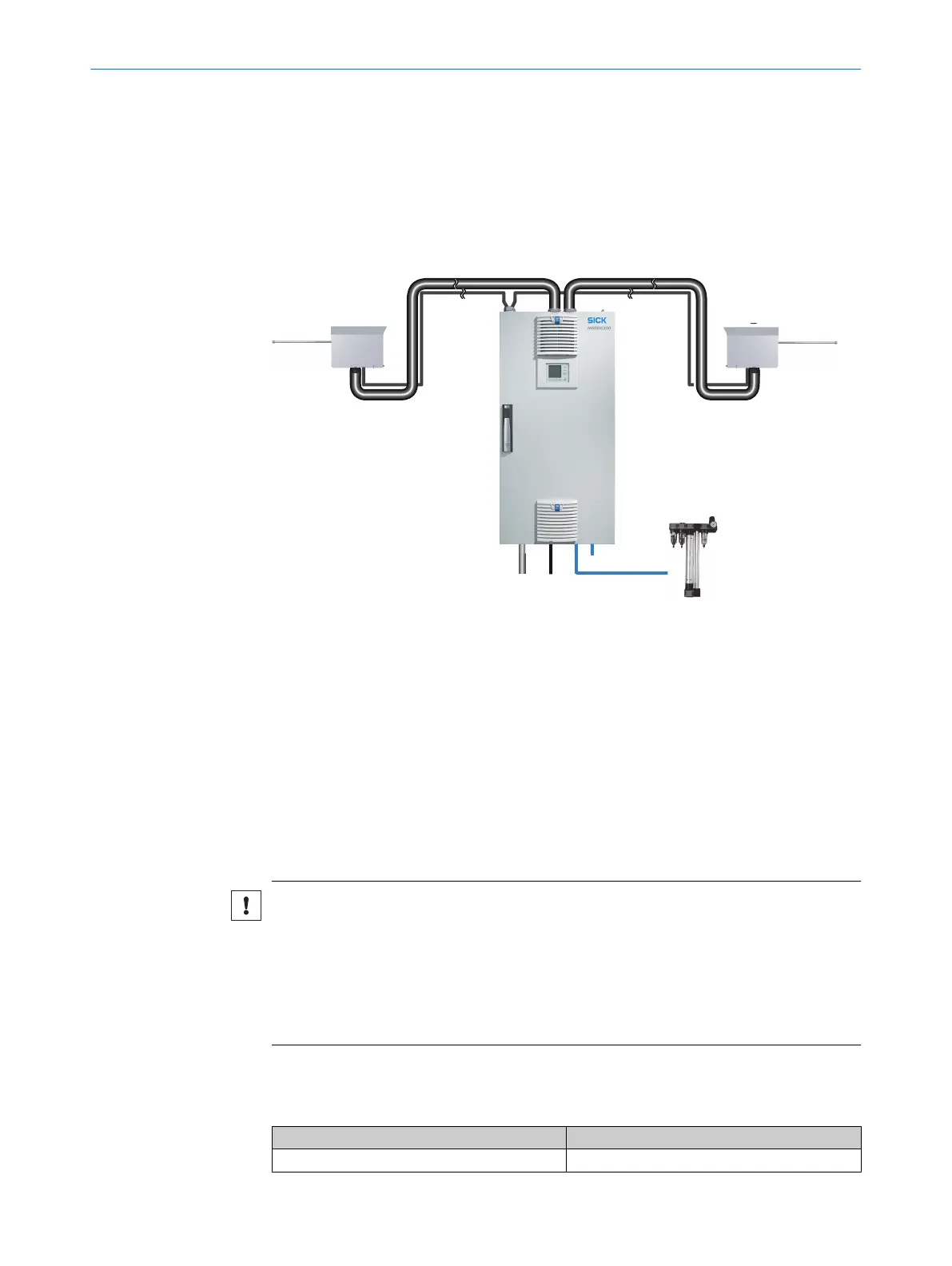
Figure 4: Installation - overview
1
Gas sampling system
2
Heated sample gas line (with 2 measuring points: 2 sample gas lines)
3
Tube bundle cable (with 2 measuring points: 2 tube bundle cables) with pneumatic and elec‐
tric lines
4
Analyzer
5
Energy supply
6
Interfaces
7
Instrument air inlet
Option: Instrument air conditioning
8
Sample gas outlet
2.6 Checklist for mechanical and electrical installation
NOTICE
Observe the sequence during installation. Connect the gas sampling units on the
exhaust duct as last task.
Incorrect assembly can create a risk of contaminating the gas extraction system. In this
case, exhaust gas can penetrate the unheated analyzer and possibly condensate.
1. First connect instrument air and power supply.
2. Then install the gas sampling system in the exhaust duct.
Observe laying information (Chapter see "Assembly information for sample gas lines
and tube bundle cable", page 11).
Table 3: Fitting and connecting system components
System component Reference
Install analyzer cabinet see "Installing the analyzer cabinet", page 13
2 INSTALLATION
10
T E C H N I C A L I N F O R M A T I O N | MARSIC300 8017585/YXD9/V3-1/2017-05 | SICK
Subject to change without notice