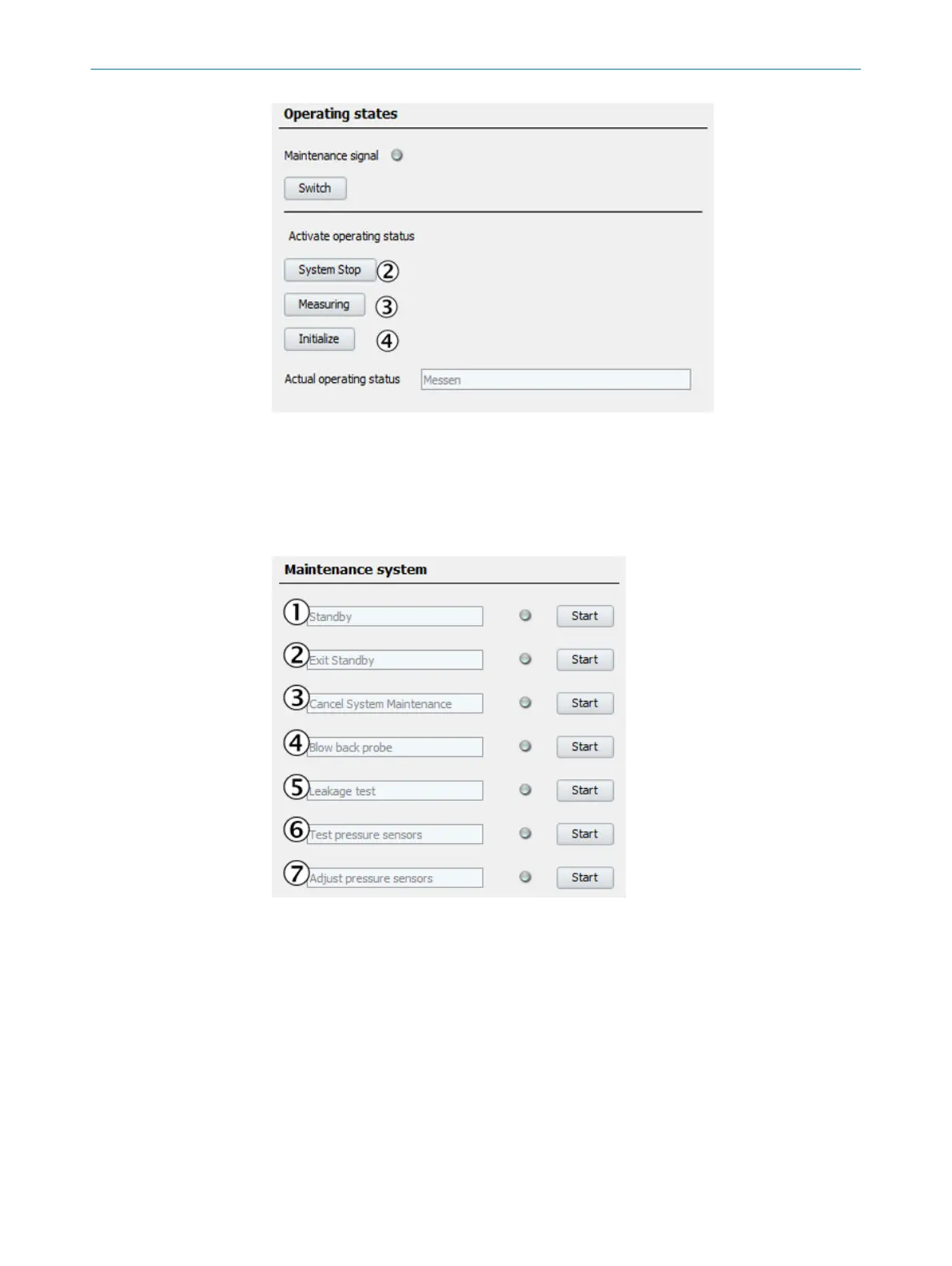
Figure 107: Menu Operating states
1
Switch button:
LED on:
Status signal “Mainte‐
nance” is switched on.
2
System Stop.
3
Switch to measuring
operation.
4
Switch to measuring
operation (after
changes in menu:
Parameterization/Meas‐
uring components/...).
8.3 System maintenance (Stand-by, Leakage test, etc.)
Menu: Maintenance/Maintenance System
This menu serves to start various maintenance procedures.
Figure 108: Menu System maintenance
1
Standby
Switches the system to Standby to put it out of operation for some time.
2
Exit Standby
Switches the system back to regular measuring operation.
(After it was switched to Standby using item "1" of this menu).
3
Cancel system maintenance
Abort a program started in this menu.
8 MAINTENANCE
70
T E C H N I C A L I N F O R M A T I O N | MARSIC300 8017585/YXD9/V3-1/2017-05 | SICK
Subject to change without notice