PT100 DIGITAL INPUTS DIGITAL OUTPUTS VALVE OUTPUTS
100
100
gnge
sw 2
sw 1
sw 3
sw 4
sw 5
sw 6
PT100 I
PT100 II
Heizkreis I
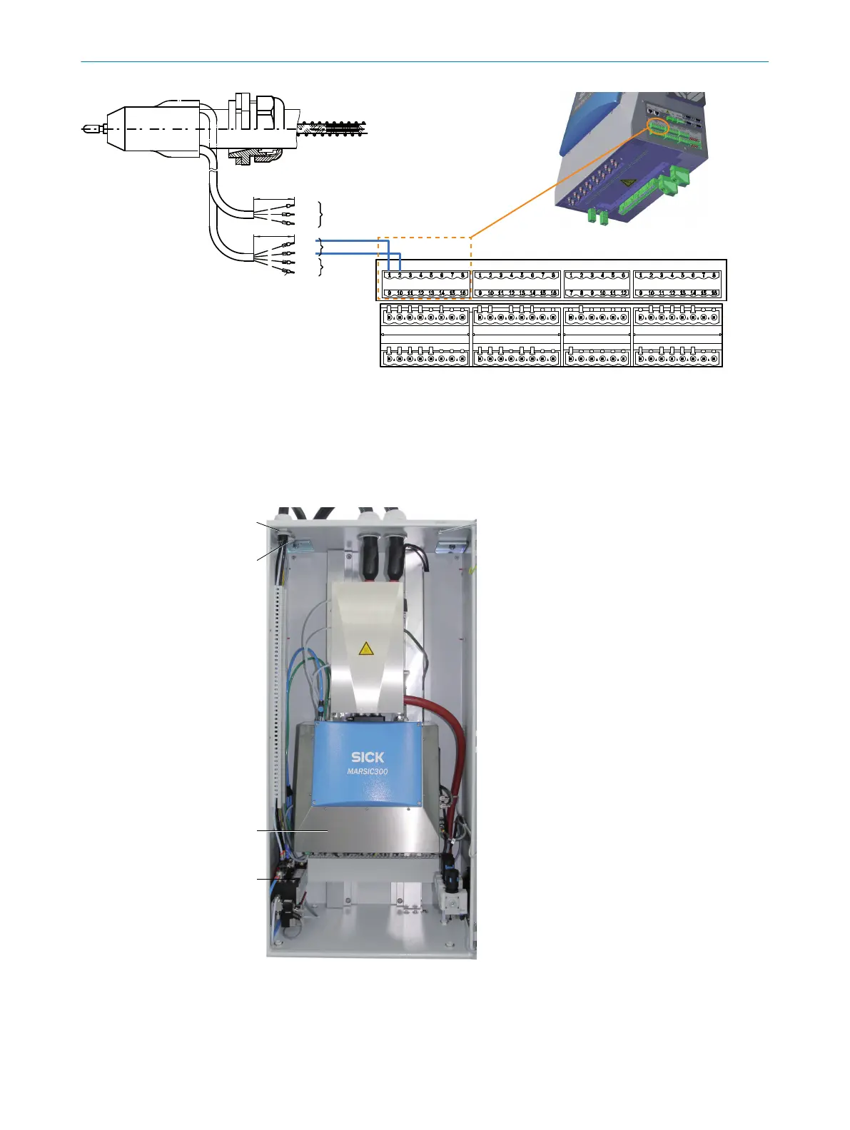
Figure 10: Pt100 connection
Complete description of the interface on page 86.
15. Connect Pt100 from the sample gas line 2 to pins 9 and 10.
2.10 Connecting the tube bundle cable to the analyzer
Figure 11: Analyzer - overview
1
Tube bundle cable 1
2
Tube bundle cable 2 (optional)
3
Valve block
4
Electronics unit
2 INSTALLATION
16
T E C H N I C A L I N F O R M A T I O N | MARSIC300 8017585/YXD9/V3-1/2017-05 | SICK
Subject to change without notice