4. Remove the thermal insulation from the existing line and remove the line.
5. Lead a new line through the enclosure duct at the bottom on the enclosure floor
and connect it to the sample gas outlet of the cell.
6. Refit the fixing.
7. Refit the thermal insulation.
8. Close cell again.
To lengthen the existing hose piece: No cross-section narrowing may occur when con‐
necting the lengthening hose.
Sample gas outlet on housing:
Figure 20: Sample gas outlet - enclosure under‐
side
1
Sample gas outlet at bottom rear of the
housing
2.13 Electrical connections on the analyzer
Connect power supply
ATTENTION
The analyzer power supply is configured for an individual power system
Check the configured power system against the system documentation provided.
b
If the analyzer power system does not match the power system on board: Please
contact SICK Customer Service.
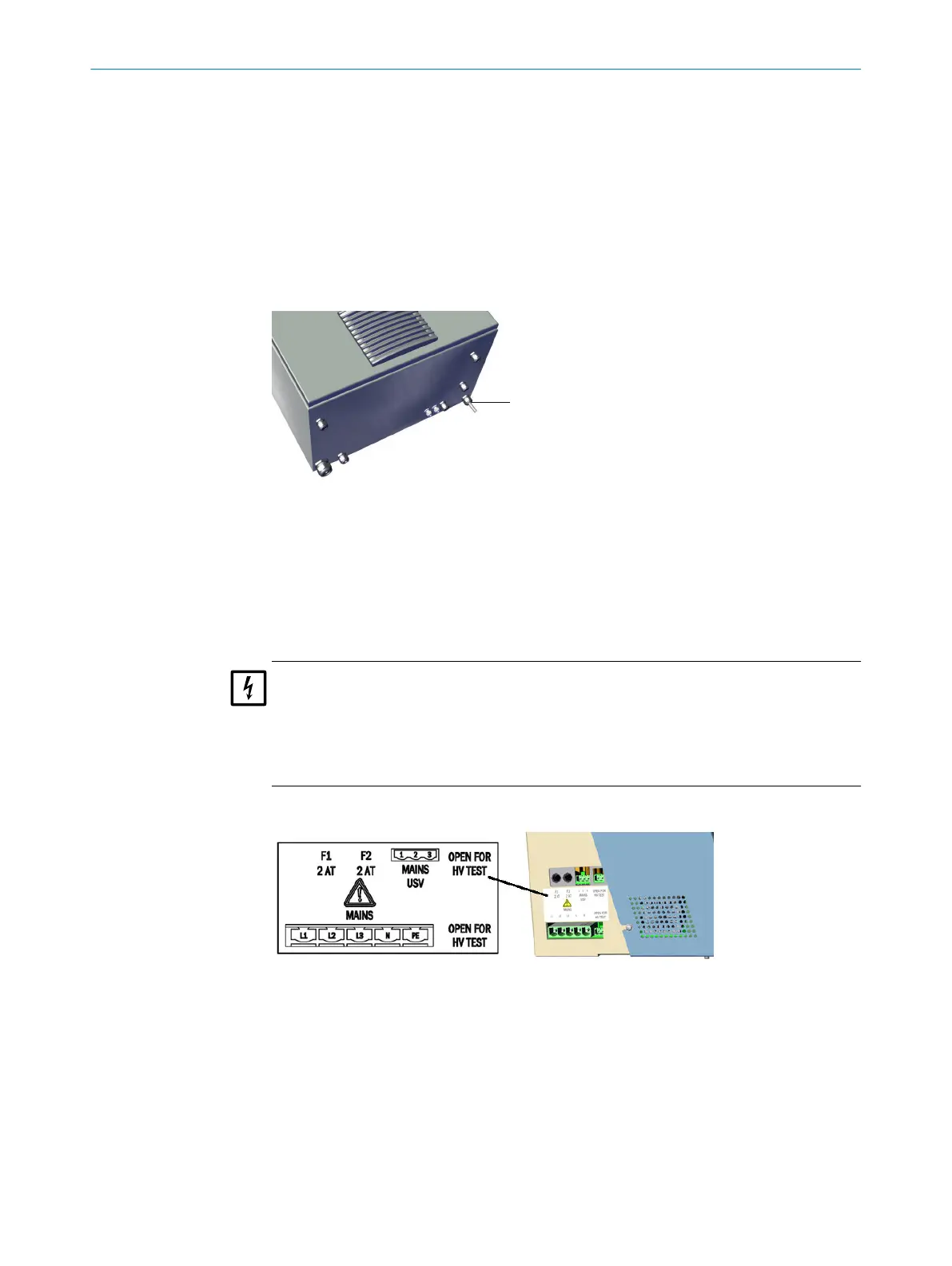
The power supply is located on the left on the analyzer.
Figure 21: Power supply connections
INSTALLATION 2
8017585/YXD9/V3-1/2017-05 | SICK T E C H N I C A L I N F O R M A T I O N | MARSIC300
23
Subject to change without notice