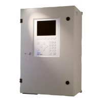
2.8 Installing the analyzer cabinet
Ø 12
1200
1254
1230
20
400
460
600
Figure 6: Analyzer cabinet - dimensional drawing
NOTICE
Observe clearances:
•
Top: 30 cm
•
Bottom: 20 cm
•
Observe the clearances for the heated sample gas line.
•
Install the analyzer in a well ventilated room at a location, when possible, with con‐
stant temperature conditions.
•
Observe the relevant ambient conditions: see "Ambient conditions", page 80.
•
Attach the enclosure with the mounting brackets provided on a suitable wall with
sufficient load-bearing capacity.
•
Secure the enclosure with 4 x M10 screw fittings (2 at bottom, 2 at top) with prop‐
erty class 8.8 (or higher).
INSTALLATION 2
8017585/YXD9/V3-1/2017-05 | SICK T E C H N I C A L I N F O R M A T I O N | MARSIC300
13
Subject to change without notice

 Loading...


