Tube bundle cable
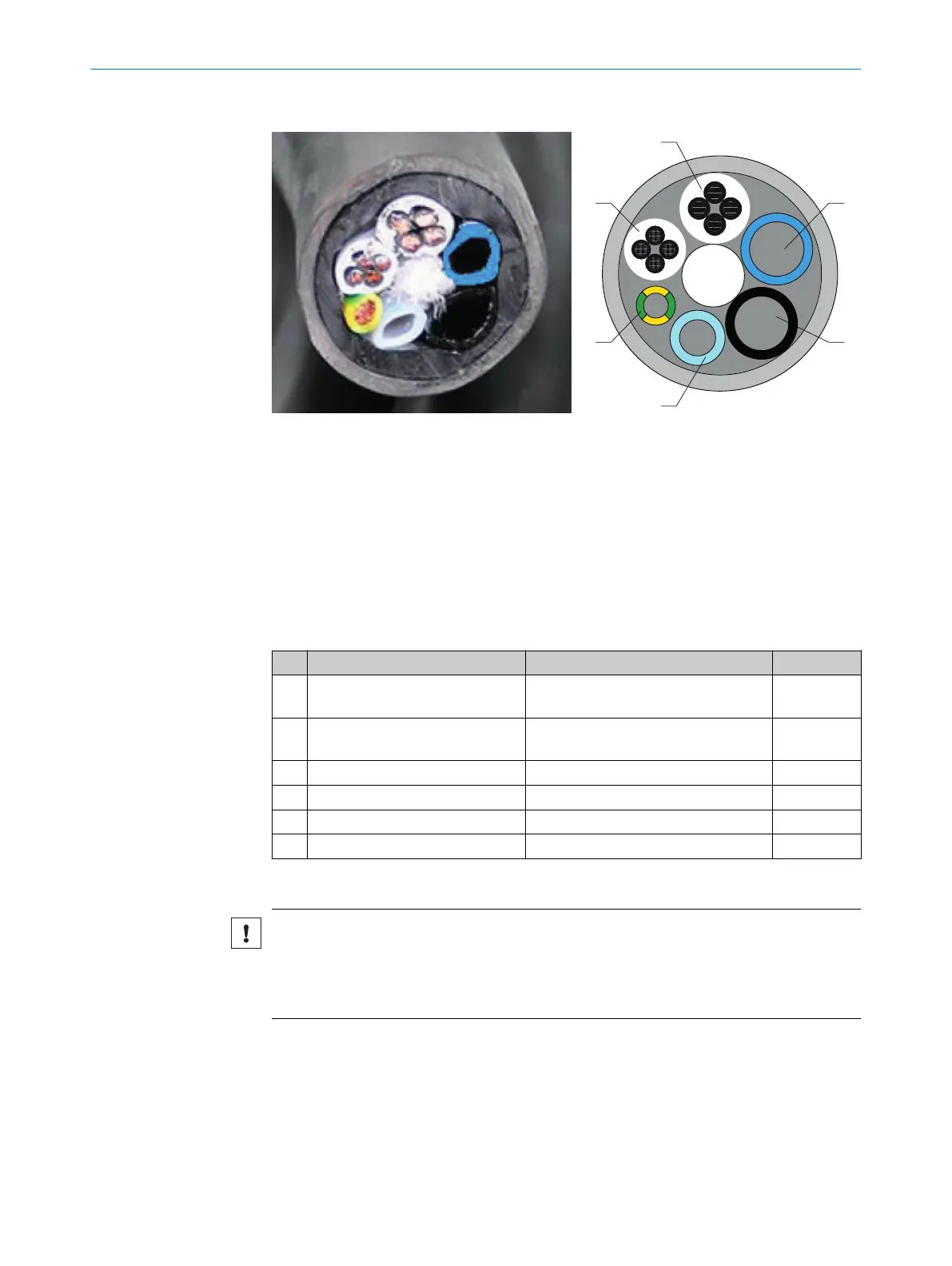
Figure 24: Tube bundle cable - overview
1
Power supply
2
Pt100 lines
3
Grounding conductor
4
PTFE tube DN4/6
5
PA tube black DN6/8; Imprint “1”
Connections on analyzer and gas sampling probe must match
6
PA tube black DN6/8; Imprint “2”
Connections on analyzer and gas sampling probe must match
No. Name Function Dimension
1
Power supplies Lines 1 and 2: Gas sampling filter
Lines 3 and 4: Probe tube (optional)
4 x 1.5 mm
2
2
Signal lines (Pt100) Lines 1 and 2: Gas sampling filter
Lines 3 and 4: Probe tube (optional)
4 x 1.0 mm
2
3
Grounding conductor (gnge) Ground 1 x 4.0 mm
2
4
PTFE hose (white) Zero gas DN 4/6
5
PA hose (black) Control air, main valve DN 6/8
6
PA hose (blue) Backflush air DN 6/8
Fit the gas sampling system on the flange
NOTICE
Risk of contamination of gas sampling system
b
First install the gas sampling system on the exhaust duct just before the analyzer
is switched on.
b
Install the gas sampling system: See “SFU Gas Sampling System Operating
Instructions”.
2.15
Setting up the Modbus-Profinet converter (optional)
As an option to Modbus, the MARSIC300 can also be configured with a Profinet or Profi‐
bus protocol. This requires an external Modbus-Profinet converter that may require
some adjustments.
INSTALLATION 2
8017585/YXD9/V3-1/2017-05 | SICK T E C H N I C A L I N F O R M A T I O N | MARSIC300
27
Subject to change without notice