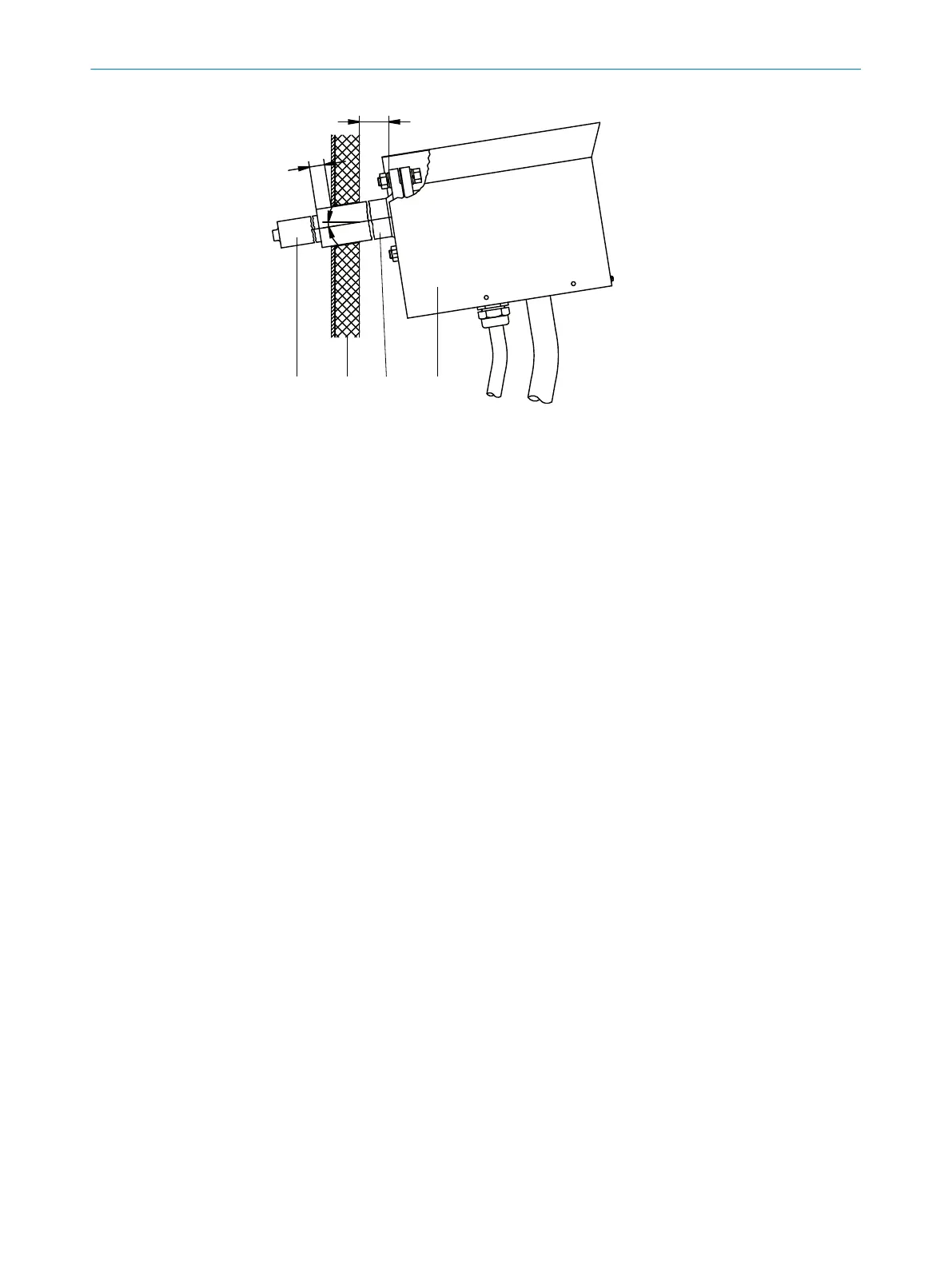
Figure 23: Flange assembly
1
Probe tube
2
Stack wall
3
Welding neck flange
4
Gas sampling filter
Gas connections
b
Connect the following gas connections on the gas sampling system:
°
Heated sample gas line
°
Tube bundle cable
•
Black line 1: Main valve
•
Blue line 2: Backflush
•
White PTFE tube: Instrument air/test gas
Electrical connections
b
Connect the following electric lines of the tube bundle cable on the gas sampling
system:
°
Power supply, gas sampling system
°
Power supply, probe tube (when heated)
°
Filter Pt100 line
°
Pt100 line, probe tube (optional, when heated)
2 INSTALLATION
26
T E C H N I C A L I N F O R M A T I O N | MARSIC300 8017585/YXD9/V3-1/2017-05 | SICK
Subject to change without notice