NOTICE
°
Install an external power disconnection unit which disconnects all connectors
and fuses near the analyzer.
°
The power disconnection unit must be marked clearly and be easily accessi‐
ble.
Observe the maximum power input of the complete system: see "Power sup‐
ply", page 82.
°
The onsite wiring system to the power source of the system must be installed
and fused according to the relevant regulations.
°
Always connect a protective ground to PE.
b
Route the electric lines through the screw fittings of the enclosure.
b
Connect the electric lines.
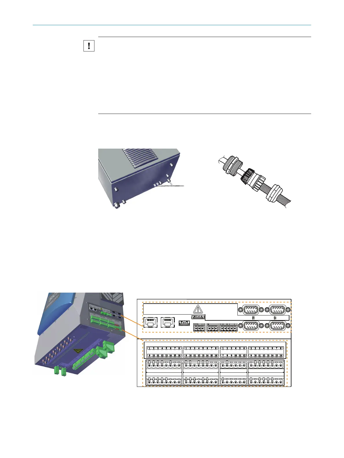
Connect signal line (optional)
1
2 x signal line ducts
b
Lead cable through the enclosure duct.
b
Attach shield as shown in the Figure above.
Connect Ethernet (optional)
ETHO ETH1 USB CAN PROFIBUS
1 2 RS422/RS485 RS232 02 DISP.
PT100 DIGITAL INPUTS DIGITAL OUTPUTS VALVE OUTPUTS
I/0-MOD.
Figure 22: Connections overview
2 INSTALLATION
24
T E C H N I C A L I N F O R M A T I O N | MARSIC300 8017585/YXD9/V3-1/2017-05 | SICK
Subject to change without notice