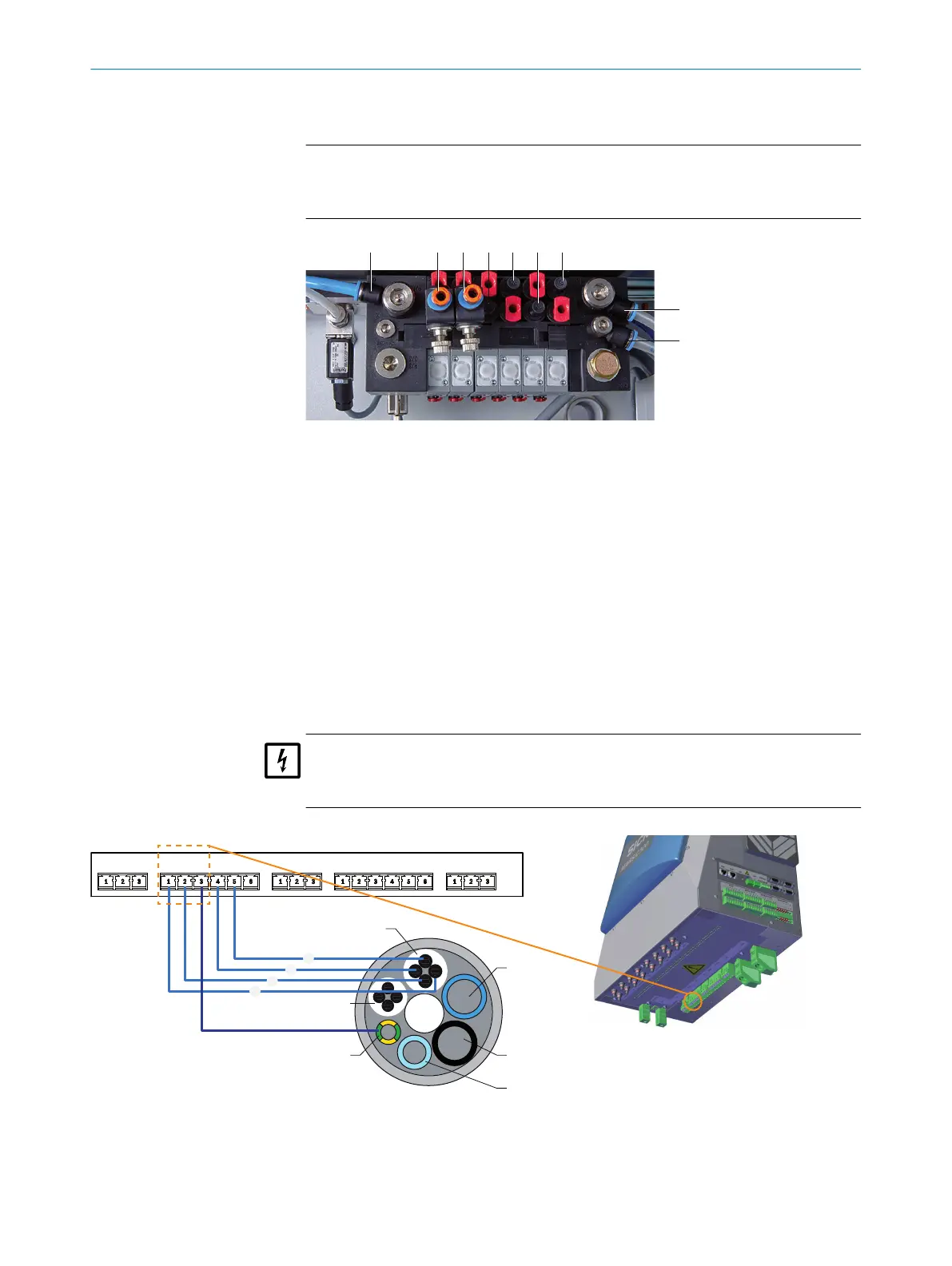
4. Connect the 3 gas lines of one tube bundle cable to the valve block (connections
marked as “outlet” in the Figure below).
NOTICE
The gas connections on the valve block must match the gas connections of the
gas sampling system (see "SFU Gas Sampling System Operating Instructions").
Figure 13: Valve block
1
Outlet: Zero gas measuring point 1
2
Outlet: Zero gas measuring point 2 (option)
3
Outlet: Control air measuring point 1
4
Outlet: Backflush air measuring point 1
5
Outlet: Control air measuring point 2 (option)
6
Outlet: Backflush air measuring point 2 (option)
7
Inlet: Zero gas
8
Inlet: Control/backflush air
9
Inlet: Auxiliary control air
-
Red plug = dummy plug
5. Connect the heating of the gas sampling system (heated sample gas filter and
optional heated probe tube).
NOTICE
The connections on MARSIC300 must match the connections of the gas sampling
system.
1
4
2
3
6
5
TUBE 1 FILTER 1 PROBE 1 FILTER 2 PROBE 2TUBE 2 TUBE 3
!
$
§
"
gnge
Figure 14: Supply lines - tube bundle cable connection diagram
Complete description of the interface, see "Tube bundle cable", page 81 Tube bundle
cable 2 optional to tube bundle cable 1.
2 INSTALLATION
18
T E C H N I C A L I N F O R M A T I O N | MARSIC300 8017585/YXD9/V3-1/2017-05 | SICK
Subject to change without notice
 Loading...


