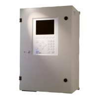
Sample conditioning and distribu‐
tion unit
Torque
Insertion of sample gas line 2 clamp‐
ing screws
1.5 Nm
Insertion of sample gas line 4 frame
screws
1.5 Nm
Solenoid valve M4 2 Nm
Cover of solenoid valve M2.5 0.35 Nm
Pump M4 2 Nm
Sample gas cooler M6 6 Nm
Enclosure, complete See above ”Analyzer“
7.12 Tube connections
Connection Dimension
Sample gas connections Swagelok DN 4/6
Instrument air Hose coupling DN 4/6
Test gas Hose coupling DN 4/6
7.13 Sample gas conditions
NOTICE
Risk of contamination of analyzer
b
Observe the specified quality of the instrument air
b
If required, provide for instrument air conditioning
Gas Quality Inlet pressure Flow rate
Instrument air Particle size max. 1 μm
Oil content max. 0.1 mg/m
3
Max. +300 hPa Typically 60 l/h
Zero point gas Nitrogen 5.0 Max. +300 hPa Typically 60 l/h
Span gas External span gas
Precision: ± 2 %
Concentration: 80% ... 100%
of measuring range
The span gas must comply
with the specifications of the
standards to be applied (e.g.,
MARPOL Annex VI)
Max. +300 hPa Typically 60 l/h
7 TECHNICAL DATA
66
T E C H N I C A L I N F O R M A T I O N | MARSIC200 8017324/15A2/V6-0/2019-10 | SICK
Subject to change without notice

 Loading...


