NOTE
Pay attention to the function indicator of the terminals!
Example: 1-X3:9 “Standby” to XD62:2 “Standby”.
Line Connection
External power supply on distribution unit Distribution unit: see "Electrical installation of distribution
unit", page 31
Power supply from distribution unit to analyzer Distribution unit: see "Electrical installation of distribution
unit", page 31
Analyzer: see chapter 2.11.3
Status signals between analyzer and distribution unit Analyzer: see chapter 2.11.3
Distribution unit: see "Electrical installation of distribution
unit", page 31
External analog and digital signals, Ethernet to analyzer Analyzer: see chapter 2.11.3
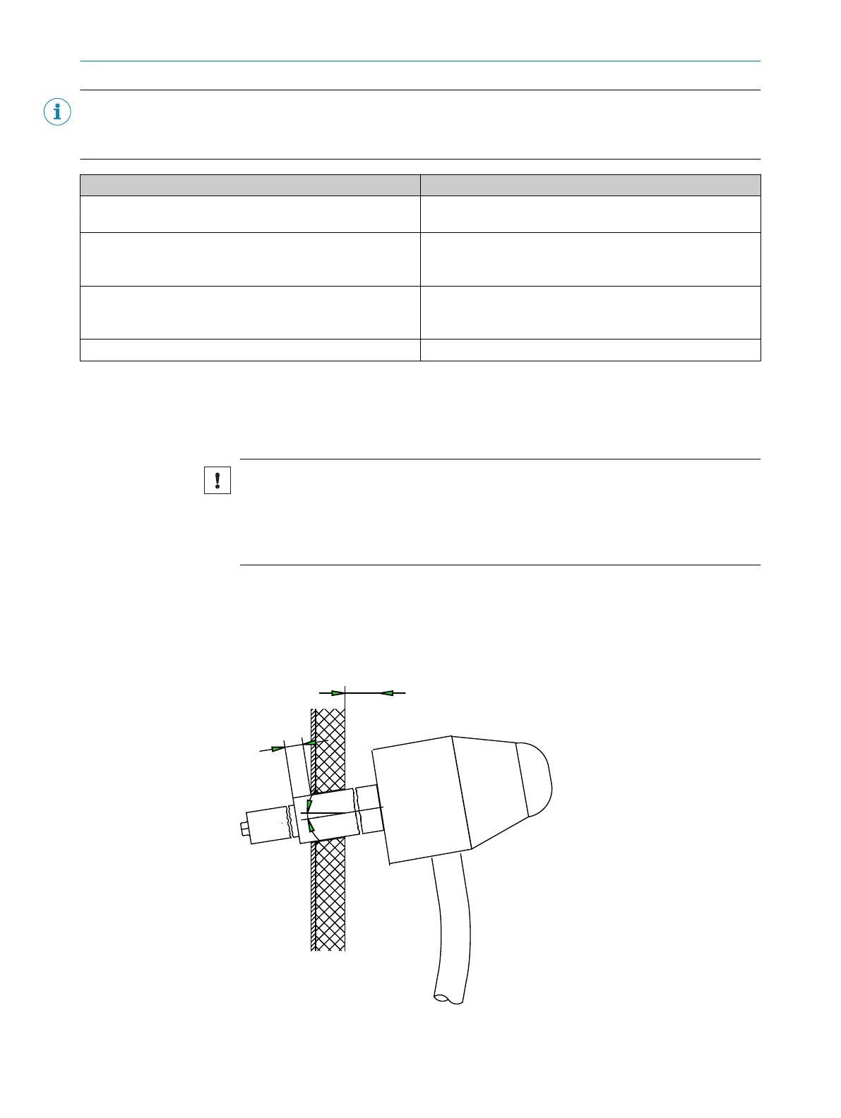
2.7 Installing the sampling probe
The sampling probe is system-specific: For information on the installation of the sam‐
pling probe, see the enclosed Operating Instructions of the sampling probe.
NOTICE
Risk of soiling the measuring system
b
First install the gas sampling system on the exhaust duct just before the analyzer
is switched on.
b
Switch the instrument air feed on immediately after installing the sampling tube.
Installation
b
Install the sampling probe in accordance with the specifications in the Operating
Instructions of the sampling probe.
w
Fit the sampling tube with the probe tip tilted down about 10°.
INSTALLATION 2
8017324/15A2/V6-0/2019-10 | SICK T E C H N I C A L I N F O R M A T I O N | MARSIC200
21
Subject to change without notice

 Loading...


