2.5 Installation overview
NOTE
Gas flow diagram see "Gas flow diagram", page 59
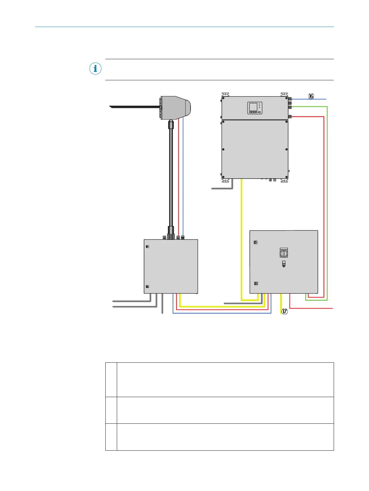
Figure 2: Installation - overview
Red Power supply
Blue and green Signal line
Yellow PTFE gas line
1
Heated sampling probe with:
•
Sampling tube
•
Sample gas filter
•
Backflushing
2
Heated sample gas line, sampling probe - sample conditioning:
•
Sample gas
•
Instrument air/test gas (optional)
3
Lines, sampling probe - sample conditioning
•
Power supply of the sampling probe
•
Signal line
INSTALLATION 2
8017324/15A2/V6-0/2019-10 | SICK T E C H N I C A L I N F O R M A T I O N | MARSIC200
11
Subject to change without notice