Operating Instructions Chapter 11
WSU/WEU26-3
8013338/YTA4/2016-03-24 © SICK AG • Industrial Safety Systems • Germany • All rights reserved 43
Subject to change without notice
Annex
11.4 List of illustrations
Fig. 1: Key data for the WSU/WEU26-3 devices............................................................10
Fig. 2: Diagnostics LEDs WSU26-3 ...............................................................................12
Fig. 3: Diagnostics LEDs WEU26-3 ................................................................................12
Fig. 4: Access guarding with WSU/WEU26-3 .................................................................13
Fig. 5: Safety distance S to the light beam ....................................................................15
Fig. 6: Minimum distance to reflective surfaces............................................................17
Fig. 7: Graph, minimum distance from reflective surfaces............................................17
Fig. 8: Mounting two WSU/WEU26-3 devices in series .................................................18
Fig. 9: Mounting possibilities using mounting brackets.................................................19
Fig. 10: Hazardous area protected on several sides........................................................20
Fig. 11: Two-beam protection with one system WSU/WEU26-3 ......................................21
Fig. 12: Incorrect alignment of sender and receiver ........................................................21
Fig. 13: Correct alignment of sender and receiver...........................................................21
Fig. 14: Assignment of the sensor contacts, sender WSU26-3........................................23
Fig. 15: Assignment of the sensor contacts, connection diagram WEU26-3 on
UE43...................................................................................................................24
Fig. 16: Circuit for an inductive load ................................................................................25
Fig. 17: WSU26-3 sender unit and WEU26-3 receiver unit..............................................26
Fig. 18: Mounting the laser alignment aid AR60 .............................................................27
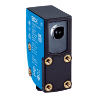
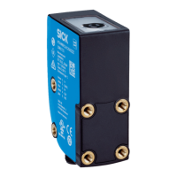
Fig. 19: WSU/WEU26-3 ...................................................................................................37
Fig. 20: Deflector mirror PSK1.........................................................................................37
Fig. 21: Bracket for PSK1 deflector mirror 1....................................................................37
Fig. 22: Spring fastening for deflector mirror PSK1.........................................................38
Fig. 23: Deflector mirror PSK45 (M = Middle of the mirror surface)................................38
Fig. 24: Mounting bracket WSU/WEU ..............................................................................38
Fig. 25: Arc-suppression element 115 ... 230 V ..............................................................38
Fig. 26: Arc-suppression element 24 V............................................................................39
Fig. 27: Dust protection tube ...........................................................................................39
Fig. 28: Weather protection .............................................................................................39
 Loading...


