Operating Instructions Chapter 5
WSU/WEU263
8013338/YTA4/2016-03-24 © SICK AG • Industrial Safety Systems • Germany • All rights reserved 25
Subject to change without notice
Electrical installation
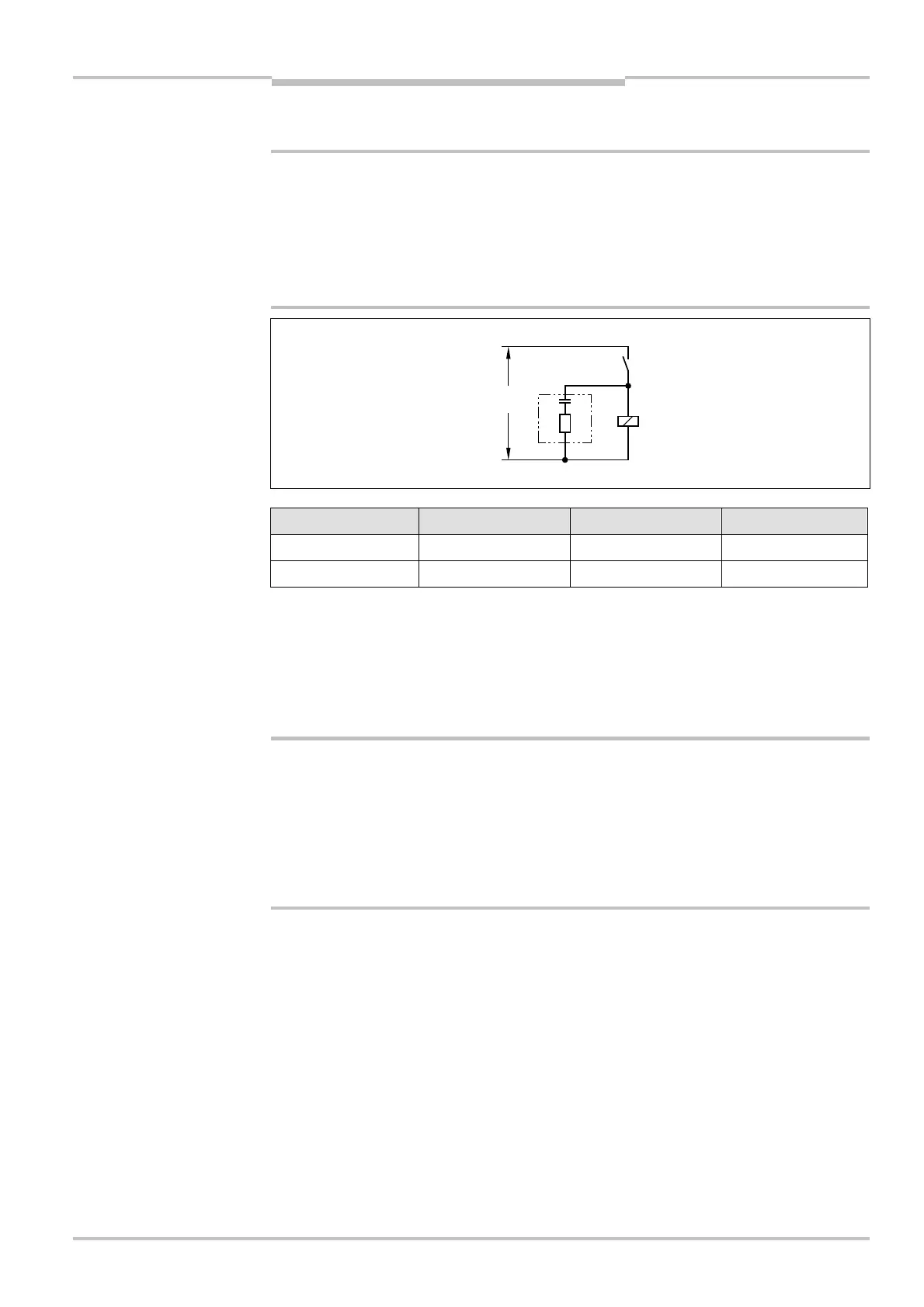
5.3 Arc-suppression
I
n case of an inductive load: Use arc-suppression elements!
Suitable arc-suppressors must be connected in parallel with the inductance. Connection in
parallel with the output contact is not permitted. Please also note that the selection of the
suppressors can increase the total switch off times.
S
uppression diodes should not be used as arc-suppressors, as they considerably increase
the switch off time. RC elements are more suitable than varistors.
Supply voltage Part No. R C
115 ... 230 V 6001224 220 U 0.22 VF
24 V 6001225 100 U 2.2 VF
Design: encapsulated in plastic; Connection wires NYAF Ø 0.5 with cable lug; Mounting
using adhesive film or cable tie.
5.4 Cross-circuit monitoring
The cables for the relay contacts are not monitored for cross-circuits by the WEU26-3.
Suitable measures
Take suitable measures for cross-circuit monitoring.
These can be:
• laying cables from the WEU26-3 to the loads protected against cross-circuits,
• screening output cables separately and connecting screen to 0 V,
• integration of the two normally open contacts at different voltage levels.
5.5 Overcurrent protection (fuse)
A fuse is to be installed in the control circuit with a rating to suit the maximum current on
the output relay.
WARNING
inductive load
suppressors
WARNING
voltage
WEU26-3
C