Chapter 4 Operating Instructions
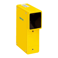
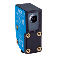
WSU/WEU263
14 © SICK AG • Industrial Safety Systems • Germany • All rights reserved 8013338/YTA4/2016-03-24
Subject to change without notice
Mounting
4 Mounting
T
his chapter describes the preparation and completion of the installation of the
WSU/WEU26@3 devices:
• calculating the necessary safety distance,
• calculating the distance from reflective surfaces,
•
mounting the device.
The following steps are necessary after mounting:
• complete the electrical connections (chapter 5),
• alignment of senders and receivers (chapter 6.1),
• testing the installation (chapter 6.2).
No protective function without sufficient safety distance!
The reliable protective effect of the single-beam photoelectric safety switches depends on
the WSU/WEU26@3 devices being mounted with the correct safety distance from the
hazardous point.
4.1 Preparation for mounting
4.1.1 Safety distance for access protection
A safety distance must be maintained between the protective field and the hazardous
point. This safety distance ensures that the hazardous point can only be reached after the
dangerous state of the machine has been completely stopped.
The safety distance as per EN ISO 13855 and EN ISO 13857 depends on:
• stopping/run-down time of the machine or system (The stopping/run-down time is
shown in the machine documentation or must be determined by taking a
measurement.),
• response time of the entire protective device,
• reach or approach speed,
• number of beams/beam separation.
Under the authority of OSHA and ANSI the safety distance as specified by
ANSI B11.19 (Annex D) E.4.2.3.3.5 and Code of Federal Regulations, Volume 29,
Part 1910.217 ... (h) (9) (v) depends on:
• stopping/run-down time of the machine or system (The stopping/run-down time is
shown in the machine documentation or must be determined by taking a
measurement.),
• response time of the entire protective device,
• reach or approach speed,
• other parameters that are stipulated by the standard depending on the application.
WARNING

 Loading...


