OUT 1
2
LSR ON
OUT
SET RUN
T
1
2
12 3 4 5 6 7 8
â àá ß 9
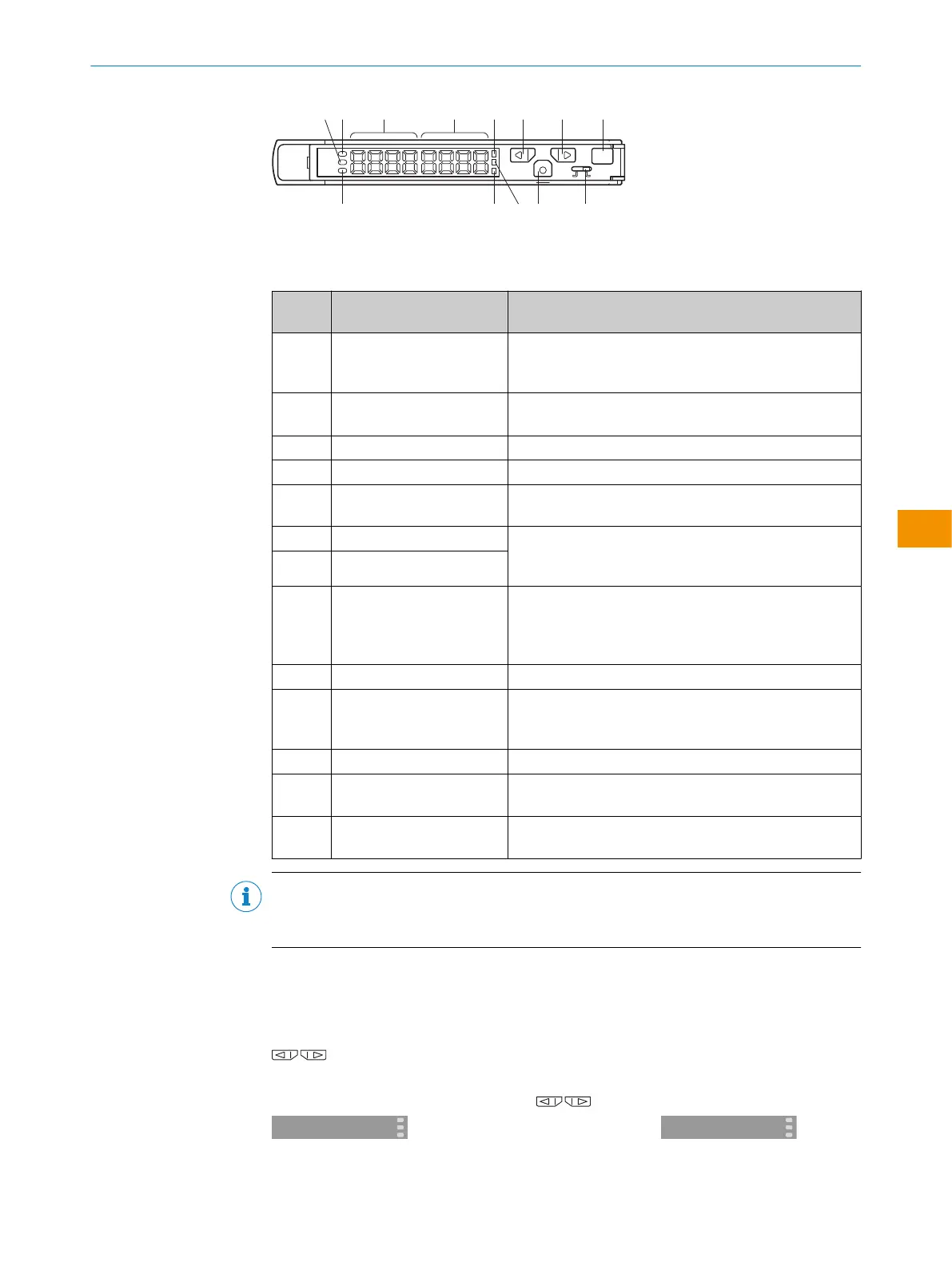
Figure 1: Function buttons
Table 1: Status indicators and function buttons of the evaluation unit
Legend
number
Name Function
1
LSR ON Laser LED
Switches on when the evaluation unit is supplied with
power.
2
OUT 1 Output LED
Lights up if 1x Out is switched on.
3
Secondary indicator (green) Shows thresholds, function selection and quantity.
4
Main indicator (red) Shows light strength, function and quantity
5
LED for the current channel
(1x Out)
Is permanently on when the display shows value, setting
and function for 1x Out.
6
UP switch Operating mode: Displays the threshold
Configuration mode: Function selection or changing the
numerical value
7
DOWN switch
8
Teach-in button Operating mode: Changes the channel.
Configuration mode: Returns to operating mode or per‐
forms scaling.
Configuration mode: Starts the teach-in.
9
Setting/operation button Changes between teach-in and operating mode.
ß
Mode switch Operating mode: Changes to configuration mode.
(0.5seconds ≥)
Configuration mode: Applies setting.
à
Teach-in LED Lights up during teach-in mode
á
OUT 2 Output LED
Lights up if 2x Out is switched on.
â
LED for the current channel
(2x Out)
Is permanently on when the display shows value, setting
and function for 2x Out.
NOTE
WI130T-P/N340 are 1x Out output type, 3 and 8 do not light up. Channel selection of
á is redundant.
Locking the control elements
Quits all operations.
Useful for avoiding errors
In RUN mode, press the switches simultaneously for two seconds or more. Do
the same to unlock.
Locking
←→
Unlocking
OPERATING INSTRUCTIONS
8020148.1HRJ/2023-02-08 | SICK O P E R A T I N G I N S T R U C T I O N S | Evaluation unit WI130
37
Subject to change without notice
en
 Loading...
