AC MUM0040 rev. 11 - 17 -
MR12 - MR12C
11. ELECTRICAL CONNECTIONS
Before making the electrical connecons, installers MUST make sure
that the mains voltage matches the technical specicaons and the
data on the winch idencaon plate.
All electrical connecons must be made with the main
switch in the OFF posion.
Make sure that the rated supply voltage is maintained
at all mes.
If they match, connect the electric motor.
1 ELECTRIC MOTOR
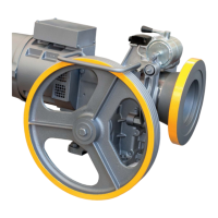
Using the wiring diagram (which can be found in the motor terminal
box), make the electrical connecons and make sure that you connect
the phases and earth correctly.
IMPORTANT NOTE
Any thermistors on the motor MUST BE CONNECTED TO A
SPECIFIC RELAY ONLY.
Incorrect connecon of the thermistors will burn them out immedia-
tely.
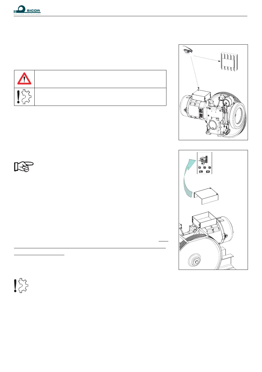
2 AUXILIARIES
Connect any auxiliaries by referring to the wiring diagram placed
under the terminal box cover or enclosed with this manual.
Check that the tension of the installed brake corresponds to that of
its dedicated charger, check that the coil connecons correspond to
those indicated in the diagram under the terminal board cover. The
installer is responsible for providing a suitable surge suppressor to
protect the brake coil.
Please also remember to check the fan voltage and power frequency.
Aer connecng, close the terminal box.
In any motor conguraon, always connect the correct voltage (V~) to terminals 3, 4 of the
fan.
.
CAPACITOR 2mF 400V
THERMOSTAT
12
11
10
9
8
7
6
5
4
3
ECD
(-) 2
(+) 1
TACHOMETER
THERMISTORS MAX 3V
FAN 220V
BRAKE
BROWN
G
FAN
- WHITE
- RED
- WHITE
- WHITE
- BLACK
- BLUE
- WHITE
- BROWN
- BLUE
M
TWO SPEED MOTORS
CONNECTION
ONE SPEED MOTORS
CONNECTION
ONE SPEED MOTORS
CONNECTION
U1
V1
W1
U2
V2
W2
U
V
W
U
V
W
V
W
U
U
V
W
2U2
2V2
2W2
2U1
2V1
2W1
1U1
1V1
1W1
1U2
1V2
1W2
2U2
2V2
2W2
2U1
2V1
2W1
1U1
1V1
1W1
1U2
1V2
1W2
HIGH SPEEDLOW SPEED HIGH SPEEDLOW SPEED
CONNECTION
CONNECTION
COLLEGAMENTO MOTORE