15
614 6
2 2 019
-
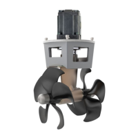
SH 360
MC_0107
Technical Specifi cations
EN
1)
Max. thrust: 182kg
2)
Max. thrust: 228kg
3)
Max. thrust: 211kg
4)
Max. thrust: 269kg
5)
Max. thrust: 302kg
6)
Max. thrust: 307kg
7)
Max. thrust: 310kg
8)
Max. thrust: 370kg
9)
Max. thrust: 399kg
60 % 80 % 100 %
Thruster model Motor type Flow Pressure Flow Pressure Flow Pressure
SH 100
U6
L/min -Bar 18.8 103 21.7 137 24.2 172
USG-PSI 5.0 1494 5.7 1987 6.4 2494
U8
L/min -Bar 25.5 77 29,9 103 32,3 129
USG-PSI 6.6 1117 7.6 1494 8.5 1871
U10
L/min -Bar 31.3 62 36.1 82 40.4 103
USG-PSI 8.3 899 9.5 1189 10.7 1494
SH 160
U6
L/min -Bar 18.6 150 21,5 200 24 250
USG-PSI 4.9 2175 5.7 2900 6.3 3625
U8
L/min -Bar 24,8 112 28.6 150 32.0 187
USG-PSI 6.6 1624 7.6 2175 8.5 2712
U10
L/min -Bar 31.0 82 35.8 120 40,0 150
USG-PSI 8.2 1305 9.5 1740 10.6 2172
U11
L/min - Bar 34.1 82 39.3 109 44.0 136
USG-PSI 9.0 1189 10.4 1581 11.6 1972
U14
L/min -Bar 43.1 64 49.7 86 55,6 107
USG-PSI 11.4 928 13.1 1247 14.7 1552
SH 240
U8
L/min -Bar 19.1 217 21.4 275 21,4 275
1)
USG-PSI 5.05 3147 5.65 3988 5.65 3988
1)
U10
L/min -Bar 23.8 174 27.5 232 30 275
2)
USG-PSI 6.29 2523 7.23 3364 7.93 3988
2)
U11
L/min -Bar 26.2 158 30.2 211 33,8 264
USG-PSI 6.9 2291 8.0 3060 8.9 3828
U14
L/min -Bar 33.1 124 38.2 166 42.7 207
USG-PSI 8.7 1798 10.1 2407 11.3 3002
U16
L/min -Bar 38.1 109 44.0 145 49.2 181
USG-PSI 10.1 1581 11.6 2103 13.0 2625
U19
L/min -Bar 45.1 92 52.1 122 58.3 153
USG-PSI 11.9 1334 13.8 1769 15.4 2219
SH320
U11
L/min -Bar 23.8 249 24.9 274 24.9 274
3)
USG-PSI 6.29 3611 6.58 3973 6.58 3973
3)
U14
L/min -Bar 30.1 196 34.7 261 35.6 274
4)
USG-PSI 7.95 2842 9.17 3785 9.41 3973
4)
U16
L/min -Bar 34.6 171 39.9 229 43.7 274
6)
USG-PSI 9.14 2480 10.54 3321 11.55 3973
6)
BA16
L/min -Bar 33.8 172 39.0 230 43.6 287
USG-PSI 8.93 2494 10.30 3335 11.52 4162
U19
L/min -Bar 41.0 144 47.3 193 52.9 241
USG-PSI 10.83 2088 12.50 2799 13.98 3495
BA19
L/min -Bar 40.1 145 46.3 194 51.8 242
USG-PSI 10.59 2103 11.44 2813 13.69 3509
U23
L/min -Bar 49.4 121 57 162 63.8 202
USG-PSI 13.05 1755 15.06 2349 16.86 2929
SH360
U19
L/min -Bar 46.5 177 53.7 236 55 248
5)
USG-PSI 12.3 2567 14.17 3423 14.53 3597
5)
BA19
L/min -Bar 45.3 176 52.3 234 58.5 293
USG-PSI 11.97 2553 13.82 3394 15.45 4250
U23
L/min -Bar 56,3 146 65.1 195 310 310
7)
USG-PSI 14.88 2118 17.2 2828 81.89 4496
7)
BA23
L/min -Bar 54.5 146 62.3 196
70.3 245
USG-PSI 14.4 2118 16.46 2843 18.57 3553
SH400
U19
L/min -Bar 43.5 195 50.2 260 54.2 302
8)
USG-PSI 11.49 2828 13.26 3771 14.32 4380
8)
BA23
L/min -Bar 52.3 163 60.4 218 67.5 272
USG-PSI 13.82 2364 15.96 3162 17.83 3945
SH 420
U26
L/min -Bar 44.7 188 51.6 251 56.2 298
9)
USG-PSI 11.81 2726 13.63 3640 14.85 4321
9)
U29
L/min -Bar 49.8 169 57.6 225 64.3 281
USG-PSI 13.16 2450 15.22 3263 16.99 4075
BA32
L/min -Bar 48.4 151 55.8 202 62.4 252
USG-PSI 12.78 2190 14.74 2929 16.49 3654
U33
L/min -Bar 56.1 148 64.7 198 72.4 247
USG-PSI 14.82 2146 17.09 2871 19.13 3582
U37
L/min -Bar 62.1 132 71.8 176 80.2 220
USG-PSI 16.41 1914 18.97 2552 21.19 3190
BA40
L/min -Bar 61 121 70.4 161 78.7 202
USG-PSI 16.12 1755 18.6 2335 20.79 2929
SH550
BA40
L/min -Bar 69.8 158 80.5 211 90 264
USG-PSI 18.44 2291 21.27 3060 23.78 3828
P42
L/min -Bar 84.2 152 97.2 203 108.7 254
USG-PSI 22.25 2204 25.68 2944 28.72 3683
G45
L/min -Bar 89.5 142 103.4 190 115.6 237
USG-PSI 23.65 2059 27.32 2755 30.54 3437
BA45
L/min -Bar 77.8 139 89.9 185 100.5 232
USG-PSI 20.56 2016 23.75 2683 26.55 3364
U50
L/min -Bar 95 128 109.7 171 122.7 213
USG-PSI 25.10 1856 28.98 2480 32.42 3089
P52
L/min -Bar 105.1 124 121.4 166 135.7 207
USG-PSI 27.77 1798 27.77 2407 35.85 3002
BA60
L/min -Bar 104.6 106 120.8 141 135.1 176
USG-PSI 27.64 1537 31.92 2045 35.69 2552
MC_0009
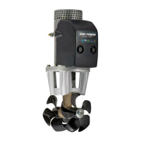
Hydraulic Thruster Installation Considerations and Precautions
EN
Before installation, The installer must read this guide to ensure necessary acquaintance with this product.
• If the height of the room you are installing the Side-Power is limited, it can be installed horizontally or at any angle in-between.
- If the electromotor is positioned more than 30º off vertical, it must be supported separately.
- The electromotor must be handled with care. Do not lift it by internal connections/ main terminals or bed placed down on the driveshaft.
- Beware of keeping installation within advised measurements. No part of the propeller or gear house must be outside the tunnel.
• Do not install the thruster in a position where you need to cut a stiff ener/ stringer/ support for the hull integrity without checking with the boat builder
this can be done safely.
• The electromotor, its components, contacts/ plugs or other joints in the control cables must be mounted so they will remain dry at all times.
• We advise painting the gear house and propellers with antifouling. (NB: Do not paint the anodes, sealings or propeller shafts)
• Do not nish the inside of the tunnel with a layer of gel coat/ topcoat or similar. There is only room for a thin coat of primer and two layers of
anti-fouling between the tunnel and the props.
• With the boat on land, run the thruster for a fraction of a second, as without resistance it will accelerate very fast to a damaging rpm.
• While the thruster is in the air, ensure that the propellers have come to a complete stop before performing a directional change of the thruster, as it
might cause damage to the thruster.
If an original Side-Power hydraulic system is NOT installed, please ensure the following:
• Install an oil lter to keep the oil clean.
• Fit an oil cooler or use an oil tank to ensure the maximum oil temperature is 43 - 50 degrees Celcius.
• Hydraulic thrusters are supplied with hydraulic motors only.
• The installed hydraulic system is the responsibility of the tter/ installer and must be within the limitations outlined in this manual to ensure no damage
is caused to the thruster.
• The hydraulic valve must have ow and pressure limits that are either set within or can be adjusted to the limits of the thrusters capability.
• We strongly advise that a shock valve is tted and set to 10% - 15% above the chosen maximum pressure set in the valve. This will prevent the
system from being damaged if the propellers are blocked for any reason.
• It is required that a device is installed to ensure that the drive direction cannot be suddenly changed, as this can severely damage the gear house.
(NB: By adding an electronic time-lapse/delay safety on the electric control system or by using a valve that has this type of protection built
in will prevent this issue. *The required time delay is 1 second.)
IMPORTANT
If installing S-link products DO NOT connect any other control equipment to the S-link controlled products except Side-Power original
S-link products or via a Side-Power supplied interface product made for interfacing with other controls. Any attempt to directly control or
at all connect into the S-link control system without the designated and approved interface will render all warranties and responsibilities
for the complete line of Side-Power products connected void and null. If you are interfacing by agreement with Sleipner and through a
designated Side-Power supplied interface, you are still required to also install at least one original Side-Power control panel to enable
effi cient troubleshooting if necessary.
 Loading...