17
614 6
2 2 019
-
SH 360
MC_0001
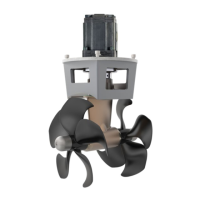
Gear Leg & Motor Bracket Installation
! Please refer to the graphic for special considerations relating to your model !
EN
1. Mark the tunnel centreline and the boat’s centreline. (NB: Install the gear leg and propeller as shown above for the thrust direction to
correspond with the control panel. Position gear leg with the P-mark facing port and the S-mark facing starboard.)
2. Use the gasket or template (recommended) to mark the hole centres and double-check the measurements. The centre hole MUST be placed using
the boat centreline as shown above. (NB: All holes must be in-line with the tunnels’ centreline for correct installation, clearance between
the propeller and the tunnel is minimal.)
3. Smooth the surface of the tunnel. A rough surface will cause possible failure/movement of the gear leg. The motor bracket must rest steadily on the
tunnel.
4. Drill the main centre hole followed by the two screw-holes.
5. Place the gear leg (without the propeller) with the gasket on inside the tunnel. Place the propeller on the gear leg to ensure it is centred and rotates
freely with the same clearance from each blade to the tunnel wall. Place top motor bracket to measure the driveshaft has come through the motor
bracket at the correct height. Remove the gear leg and propeller for nal installation.
6. Apply appropriate sealant to both sides of the gasket and place on the gear leg. Place the gear leg in the tunnel (without the propeller).
7. Install the top motor bracket and gear leg gently together. Use appropriate sealant to ensure that no leakages occur. (NB: See your sealant
datasheet for the correct application process.)
8. Fasten the gear leg and the motor bracket with the bolts provided. Fasten to torque as shown above.
IMPORTANT
Ensure that there is some oil or grease
on the O-rings in the motor bracket
before mounting it together with the
gearhouse, as no lubrication could
cause serious damage to the O-rings.
The gear leg neck and the inner surface
of the motor bracket must remain
clean.
1
1
2
2
3
3
4
4
5
5
6
6
A A
B B
C C
D D
72101/U-16
07.03.2014
1
Designed by
Date
1 / 1
Edition Sheet
gille
Material Type
Drawing nr
SM-106027
Copyright
All rights reserved
Part nr Size
Scale
Title
Hyd. motor 16 ccm
Tolerance
NS-ISO 2768-1
SLEIPNER MOTOR AS
A3
5,794 kg
1 : 2
Weight
44,8
15,00
7
1
,
4
0
8
9
,
5
0
94,00
114,00
8
,
5
0
(
4
x
)
3
5
,
7
0
1
1
2
2
3
3
4
4
5
5
6
6
A A
B B
C C
D D
72101/U-16
07.03.2014
1
Designed by
Date
1 / 1
Edition Sheet
gille
Material Type
Drawing nr
SM-106027
Copyright
All rights reserved
Part nr Size
Scale
Title
Hyd. motor 16 ccm
Tolerance
NS-ISO 2768-1
SLEIPNER MOTOR AS
A3
5,794 kg
1 : 2
Weight
44,8
15,00
7
1
,
4
0
8
9
,
5
0
94,00
114,00
8
,
5
0
(
4
x
)
3
5
,
7
0
MC_0106
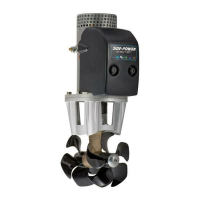
Technical Requirements / Hydraulic hose connections to motor
EN
Port A Port B Drain port
(Must be installed,
Port location varies)
Motor type Port A/B** Port fl ange threads Drain port
U6 1/2" BSP — 1/4" BSP
U8 1/2" BSP — 1/4" BSP
U10 3/4" BSP — 1/4" BSP
U11 3/4" BSP — 1/4" BSP
U14 3/4" BSP — 1/4" BSP
U16 3/4" BSP — 1/4" BSP
U19 3/4" BSP — 1/4" BSP
U26 3/4" BSP — 1/4" BSP*
U29 3/4" BSP — 1/4" BSP*
U33 3/4" BSP — 1/4" BSP*
U37 3/4" BSP — 1/4" BSP*
U37 3/4" BSP — 1/4" BSP*
U50 1" BSP — 1/4" BSP*
P42 1" 3000 PSI SAE J518/ ISO 6162 Code 61 3/8-16 UNC-2B, 22 deep 1/4" BSP*
P52 1 1/2" 3000 PSI SAE J518/ ISO 6162 Code 61 M12 x 1,75, 19 deep 1/4" BSP*
G45 1 1/4" BSP — 1/4" BSP*
BA16 1.1/16" - 12UN-2B — 9/16" UNF-18
BA19 3/4" BSP — 3/8" BSP*
BA32/ BA23 1/2" 6000 PSI SAE J518/ ISO 6162 Code 62 5/16-18 UNC-2B, 18 deep 3/4" UNF-16
BA40 3/4" 6000 PSI SAE J518/ ISO 6162 Code 62 3/8-16 UNC-2B, 20 deep 3/4" UNF-16
BA45 3/4" 6000 PSI SAE J518/ ISO 6162 Code 62 3/8-16 UNC-2B, 21 deep 3/4" UNF-16
BA60 3/4" 6000 PSI SAE J518/ ISO 6162 Code 62 3/8-16 UNC-2B, 22 deep 7/8" UNF-16
* Drain port connector must not extend internally beyond 10,5mm from end face.
** Use only parallel threaded adaptors, preferably with soft seal. Do not use plumbing tape, hemp, tread sealant or similar
products.
U, P & G-motor:
BA-motor:
Always use upper positioned
drain port for optimal lubrication
of the motor.
Pre ll motor housing with
hydraulic oil before startup
MG_0045
1
6 7
2 - 4
5
B
ØC
ØA
MODEL ØA B ØC
SH 360
68 mm
2.67”
48 mm
1.89”
12 mm
0.47”
PORT STARBOARD
S
P
TUNNEL
CENTRELINE
BOATS
CENTRELINE
BOW
TUNNEL
CENTRELINE
BOATS
CENTRELINE
SEALANT
FASTEN
33 Nm
24 lb/ft
IMPORTANT
Do not apply sealant
to the holes.