19
614 6
2 2 019
-
SH 360
MC_0109
Motor Installation
! Please refer to the graphic for special considerations relating to your model !
EN
1. Remove the 4 bolts in the motor bracket.
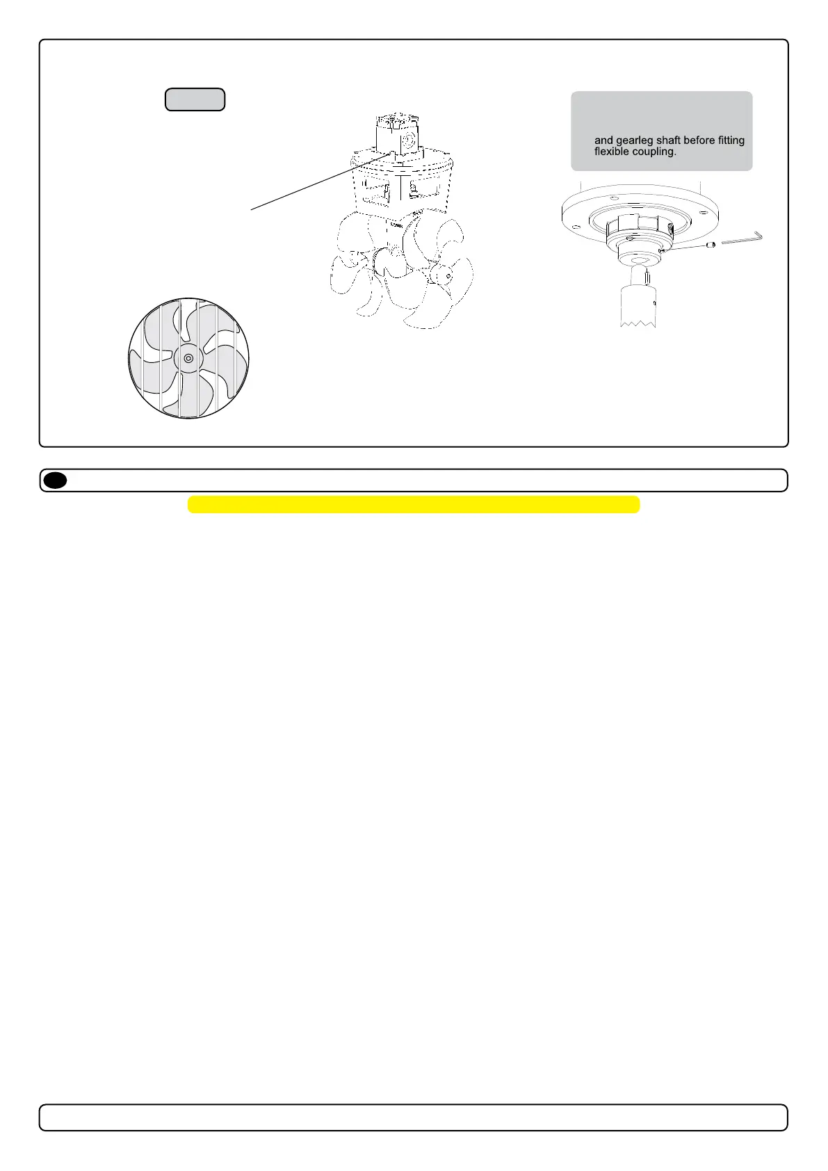
2. Turn the driveshaft in the gear house and the motor shaft so the key in the shaft and the keyway in the exible coupling align.
3. Attach the motor with its pre- tted adaptor plate onto the driveshaft and motor bracket gently.
4. Fasten the motor loosely to the bracket with the provided bolts.
5. Fasten the adaptor plate rmly to the bracket with the provided screws.
6. Secure the lower part of the exible coupling in its new position by tightening the two set-screws.
7. Fasten the bolts holding the hydraulic motor to its adaptor plate with the above torque. Apply thread glue (Locktite or similar) to the lower set screw.
(NB: Upper set screw is pre-fi tted with Loctite thread glue.)
8. Check the drive shafts engage by rotating the propeller. It is required the propeller can rotate via hand power. (NB: Rotating the propellers can be
hard because of the gear reduction and the motor.)
9. Ensure to install the drain hose. Apply the gear leg and propeller with antifouling designed for propellers. Do not apply to the propeller drive shaft,
the anodes or the end of the gear leg facing the propellers.
Only in shallow installations in workboat and shing boats we recommend protecting the propeller by installing a grid in the tunnel opening. (NB: Keep
the grid confi guration to a minimum to ensure water fl ow for the thruster is not signifi cantly aff ected. Be aware that any grid confi guration
will change the eff ectiveness of the thruster and circular profi le steel will decrease thrust signifi cantly.)
(NB: The motor must be covered to avoid dust from fabrication/ maintenance operation entering the motor or the solenoids. After fabrication
maintenance operations have ceased the cover must be removed before operating the thruster.)
MG_0149
Bolt tightening forces:
Bolts (4x) holding motor to
bracket: 33 Nm (24 lb/ft)
Fig. 1
IMPORTANT!
Apply seawater resistant
grease on both motor shaft
Propeller Installation
EN
MC_0018
! Please refer to the graphic for special considerations relating to your model !
1. Centre the drive pin and Insert the propeller onto the shaft spine. Rotate the propeller until the drive pin aligns with the internal slot in the propeller.
2. Insert the washer to the end of the shaft spline. Tighten with the propeller lock-nut.
3. Insert the anode to the end of the propeller and tighten the anode holding screw. Apply a thread glue (Loctite 243 or similar) to ensure that the
anode holding screw does not un-screw itself from during the rotation of the propeller.
4. Apply antifouling to the gear leg and propeller. Do not apply antifouling to any rubber elements of the gear leg or anodes.
MG_0033
DRIVE PIN
PROPELLER
WASHER
LOCK NUT
ANODE
ANODE HOLDING
SCREW
Apply Loctite 243 or similar
Anitfouling