10
SR80/185T - SR100/185T 1.0.0 - 2009
Model Voltage Nominal
current
draw
Min. battery
CCA
>7m total + & - 7-14m total + & - 15-21m total + & - 22-28m total + & - 28-35m total + & - 36-45m total + & -
Min. Rec. Min. Rec. Min. Rec. Min. Rec. Min. Rec. Min. Rec.
SR80/185T 12 V 530 A DIN: 550
SAE:1045
mm
2
AWG
60
2/0
70
2/0
95
3/0
2x 70
2x 2/0
2x 70
2x 2/0
2x 95
2x 2/0
2x 95
2x 3/0
270* 2x 120
2x 4/0
340* NA NA
24 V 260 A DIN: 300
SAE: 570
mm
2
AWG
25
1
35
1
35
1
50
1/0
60
2/0
70
2/0
70
2/0
95
3/0
95
3/0
120
4/0
120
4/0
2x 95
2x 3/0
SR100/185T 12 V 740 A DIN: 750
SAE: 1425
mm
2
AWG
95
3/0
95
3/0
2x 70
2x 2/0
2x 95
2x 3/0
2x 95
2x 3/0
280* 250* 375* NA NA NA NA
24 V 340 A DIN: 400
SAE: 760
mm
2
AWG
35
1
50
1/0
50
1/0
70
2/0
60
2/0
95
3/0
95
3/0
120
4/0
120
4/0
2x 95
2x 3/0
2x95
2x 3/0
2x 120
2x 4/0
Minimum and recommended cable dimensions can be identical due to safety margins and cable heat considerations for short cable lenghts.
* Minimum or recommended cable cross section in mm
2
Battery & cable recommendations:
Elektrisk installasjon
N
• Forklaring til elektrisk tabell
- Kabellengder tilsvarer + kabelen, og - kabelen (Frem og tilbake).
- Min. batterikap. som kaldstartkapasitet (CCA), ikke Ampere.
- Bruk trege sikringer for å forebygge spenningsfall.
• Det er viktig å bruke kabler som er store nok, og et batteri med god ka-
ldstartkapasitet for å drive thrusteren. Det er Volten som kommer frem
WLOPRWRUHQXQGHUNM¡ULQJVRPEHVWHPPHUWXUWDOOHWWLOPRWRUHQRJGHUPHG
RJVnVN\YHNUDIWHQ9UYHQQOLJRJMDPI¡UOLVWHQRYHUIRUPLQLPXP
anbefalte kabel, og batteristørrelse.
• En hovedstrømbryter (*C) som ikke medfører stor spenningsfall MÅ
installeres på thrusterens plusskabel slik at det er mulig å skru av
strømmen til thruster uavhengig av resten av det elektriske systemet,
når man ikke er om bord, eller i et nødstilfelle. Bryteren bør plasseres
SnHWWLOJMHQJHOLJVWHGRJEnWHQVLQVWUXNVPDQXDOPnWDIRUVHJDWGHQQH
skal skrus av slik som de andre hovedbrytere.
• Det må installeres sikring på pluss strømkabelen for å beskytte mot
NRUWVOXWQLQJDYKRYHGVWU¡PNDEOHQH6LNULQJHQE¡UYUHDYK¡\NYDOLWHW
noe som vanligvis betyr at de er fysisk store, for å unngå spenningsfall
som ofte er resultatet av å bruke mindre, enklere sikringer. Sikringen
VNDOYUHHQWUHJW\SHVRPWnOHUDPSHUWUHNNHWWLOHOHNWURPRWRUHQL
minimum 5 min.
• Kabelendene kan må påmonteres terminaler og disse må isoleres mot
alt som ikke er riktig kontaktpunkt.
• Det er viktig att kabelsko trekkes korrekt fast på koblingsbolt. Kontra
mutter på koblingsbolt må holdes fast ved tiltrekking (Fig. 2).
Minus kabelen (*A) tilkobles A1 (-) terminalen.
Pluss kabelen (*B) tilkobles "+" terminalen.
ø10mm / 3/8’’på motoren dra til med 15 Nm.
Electrical installation
GB
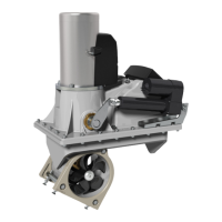
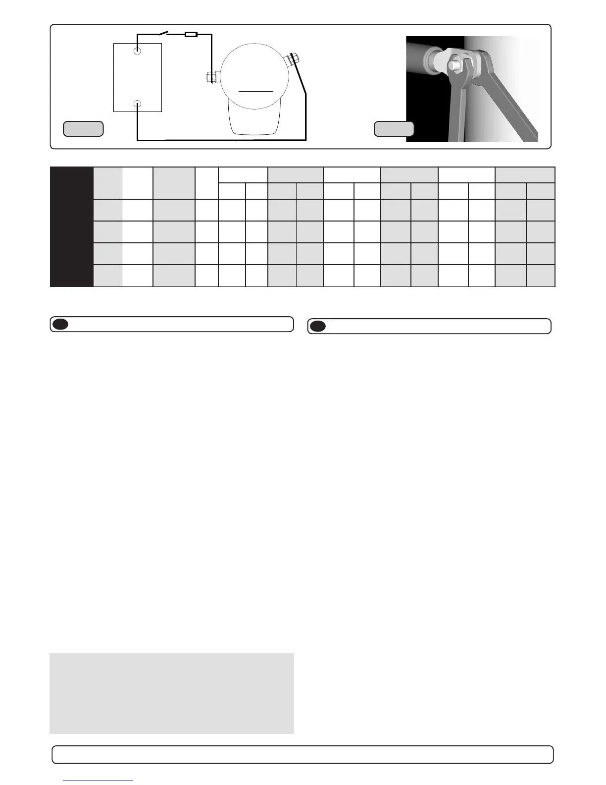
Fig. 1
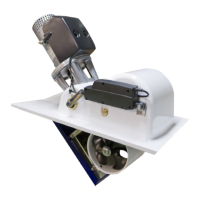
)LJ
• Explanation of electrical table
- All cable lengths are the total of + and - (to and from).
- Battery size is stated as minimum cold crank capacity, not Ah.
- Use slow fuse rated to hold stated Amp-Draw for min. 5 minutes.
• It is important that you use a good cable size and batteries with a
high cranking capacity to feed the thruster, because it is the actual
voltage at the motor while running the thruster that decides the
output rpm of the motor and thereby the actual thrust. Please see
the list below for advised min. sizes of cables and batteries. You can
of course use larger cables for even better results.
• A main switch (*C) that can take the load without noticeable voltage
drop MUST be installed in the main positive lead so the power for the
thruster can be turned off independent of the rest when not on board
or in emergencies. This should be placed in an easy accessible
place and the boats instructions should inform that this should be
turned off like the boat’s other main switches.
• We also advice to install a fuse (*D) in the positive lead for protection
against short circuiting of the main cables. This fuse should be of a
adequate quality which normally means that it is physically large as
these have less voltage drop than the simple / small ones. It should
be of the slow type and sized to take the amperage draw for at least
5 minutes.
• 7KHFDEOHHQGVPXVWEH¿WWHGZLWKWHUPLQDOVDQGWKHVHPXVWEHZHOO
isolated against contact with anything but the proper connection
point.
• Terminals must be properly tightened. Secure/hold inner nut when
tightening (Fig. 2). Tighten with max: 15 Nm/11lb/ft.The negative/
minus cable (*A) connects to the A1 (-) terminal. The positive/plus
FDEOH%FRQQHFWVWRWKH³´WHUPLQDO¡PP
bolt. Tighten with 15 Nm/11lb/ft.
NB! Very important to check the following with mainswitch
in off-position:
After all electrical connections have been completed check with an
ohm meter that there is no electrical connection between electro-
motor body and positive terminal on the motor and between the
electromotor body and the negative (A1) terminal on the motor.
If you feel unsure on how to perform this check, contact skilled
personnel for guidance.
 Loading...