Fail-Safe Modules
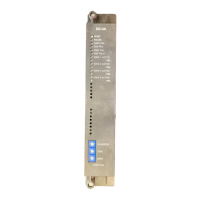
7.6 EM 4 F-DI/3 F-DO DC24V PROFIsafe digital electronic module
ET 200S Distributed I/O System - Fail-Safe Modules
Installation and Operating Manual, 08/2008, A5E00103686-07
161
Technical Specifications
Sensor supply Red VsF LED and display at channel LED
Diagnostic functions
• Group fault display
Red LED (SF)
• Diagnostic information can be displayed
Possible
Sensor Supply Outputs
Number of outputs 1
Output voltage
• Loaded
Minimum L+ (-1.5 V)
Output current
• Rated value
400 mA
• Permissible range
0 mA to 400 mA
Short-circuit protection Yes, electronic
• Operating value
4 A to 9 A
Specifications for sensor selection *
Input voltage
• Rated value
24 VDC
• For "1" signal
15 V to 30 V
• For "0" signal
-30 V to 5 V
Input current
• For "1" signal
3.5 mA, typical
Input delay *
• For "0" after "1"
Typically 3 ms (2.6 ms to 3.4 ms)
• For "1" after "0"
Typically 3 ms (2.6 ms to 3.4 ms)
Input characteristic In accordance with IEC 61131-2 Type 1
Connection of 2-wire proximity switch (BERO) Not possible
Data for Selecting an Actuator*
Output voltage
• For "1" signal • Minimum L+ (-2 V)
• P-switch: Minimum L+ (-1.5 V); voltage drop
in M-switch: 0.5 V, maximum
Output current for "1" signal
• Rated value
2 A
• Permissible range
20 mA to 2.4 A
For "0" signal (residual current) 0.5 mA, maximum
Indirect control of load by means of interface
relay:
For "0" signal (residual current) 0.5 mA, maximum
Load resistance range 12 Ω to 1 kΩ
Lamp load 10 W, maximum
Parallel connection of 2 outputs Not possible
 Loading...