Do you have a question about the Siemens ZIC-4A and is the answer not in the manual?
Lists the key capabilities and characteristics of the ZIC-4A module.
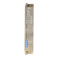
Describes the front panel controls and the function of each LED indicator.
Details the configuration of DIP switches and jumpers before installation.
Outlines the different application types for the ZIC-4A output zones.
Provides a comprehensive table of switch and jumper settings for various zone usages.
Explains how to connect field wiring to the ZIC-4A terminal blocks.
Illustrates configurations for powering the ZIC-4A with single or multiple power supplies.
Lists the current and voltage requirements for the ZIC-4A module.
Details how to configure the ZIC-4A as a Bell Follower Primary or Secondary.
Provides wiring diagrams for supervised notification appliance circuits.
Shows wiring for connecting to a supervised municipal tie.
Illustrates wiring for connecting to a remote monitoring system.
Depicts wiring for releasing service applications, including compatible solenoids.
Details wiring for releasing service when using a PSC-12 power supply.
Illustrates the wiring for Bell Follower Primary and Secondary configurations.
Shows wiring for two-channel audio notification appliance circuits.
Depicts wiring for single-channel audio notification appliance circuits.
Illustrates wiring for combined two-channel audio and strobe circuits.
Shows wiring for combined single-channel audio and strobe circuits.
Explains the logic flow for releasing functions in specific Siemens systems.
| Brand | Siemens |
|---|---|
| Model | ZIC-4A |
| Category | Control Unit |
| Language | English |