Siemens Industry, Inc.
Building Technologies Division
P/N 315-033050-155
TROUBLE (Yellow) Normally OFF. When illuminated, indi-
cates that the ZIC-4A has detected a
trouble on Zone 2 (open circuit or short
circuit).
ZONE 3 ACTIVE (Red) Normally OFF. When illuminated, indi-
cates that Zone 3 is active.
TROUBLE (Yellow) Normally OFF. When illuminated, indi-
cates that the ZIC-4A has detected a
trouble on Zone 3 (open circuit or short
circuit).
ZONE 4 ACTIVE (Red) Normally OFF. When illuminated, indi-
cates that Zone 4 is active.
TROUBLE (Yellow) Normally OFF. When illuminated, indi-
cates that the ZIC-4A has detected a
trouble on Zone 4 (open circuit or short
circuit).
Three rotary dial switches at the bottom of the front panel are used to set the HNET
network address of the ZIC-4A.
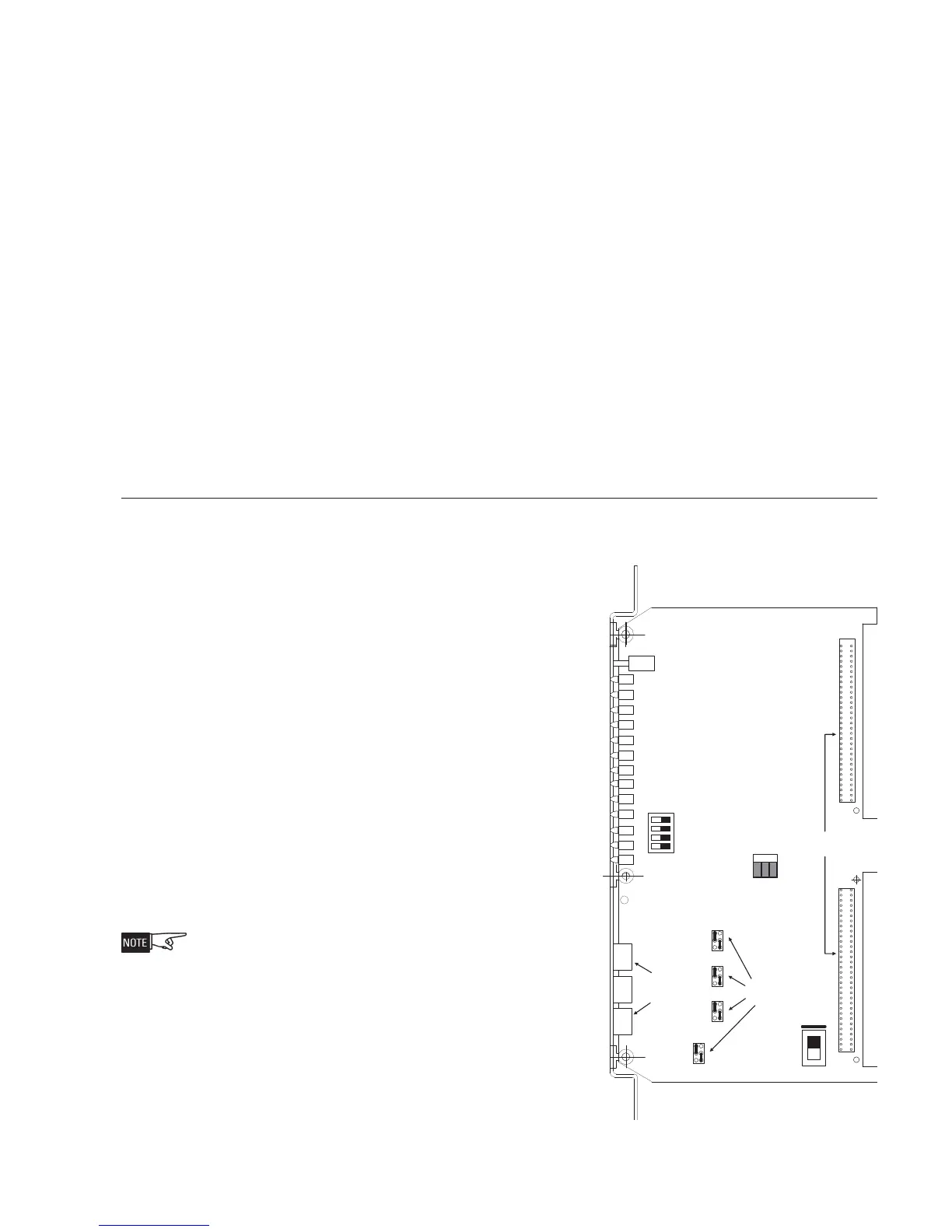
PRE-INSTALLATION The following components must be set prior to inserting the card to the CC-5 (refer
to Figure 2):
S1 Primary Bell Follower Select Switch:
This switch selects Zone 1 as the Primary
Bell Follower. Toggle the S1 switch
towards the bottom of the board if Zone
1 is configured as a Primary Bell Follower;
otherwise toggle it to the top of the
board for normal operation (as shown in
Figure 2.)
S2, Leased Line Select Switches: These
switches select the zones configured for
Leased Line application. Toggle each
switch to the ON position if the corre-
sponding zone is configured as Leased
Line. If the zone is not configured as a
Leased Line application, the correspond-
ing zone switch must be set to the OFF
position.
During card failure, Zone 1 and Zone 2
outputs will activate if the FireFinder-
XLS/Desigo Fire Safety Modular/Cerberus
PRO Modular Alarm bus is asserted,
Zone 3 outputs will activate the if the
FireFinder-XLS/Desigo Fire Safety
Modular/Cerberus PRO Modular Trouble
Bus is asserted. You must configure each
zone to the proper Leased Line remote
monitoring circuit.
Silver line on S1 and jumpers P1 and
P4 indicates normal operation.
96 PIN DIN
PLUG CONNECTOR
S4
S1
P1
P2
P3
P4
S2
S3
On
1
4
3
2
RESET
SWITCH
LEASED LINE
SELECT
ZONE INPUT
SUPR ENABLE
NETWORK
ADDRESS
S6
S7
1
4
5
6
2
3
1
4
5
6
2
3
1
4
5
6
2
3
1
4
5
6
2
3
S5
INPUT
POWER
SELECT
EXT
POWER
BP
POWER
Figure 2
ZIC-4A Switch Location