Block diagram
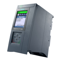
The following figure shows the block diagram of the CPU1515‑2PN.
3
4
2
5
1
L+
M
X50
PN
X1 P1R
PN
X2 P1
R/S ERSA MT
PN
X1 P2R
X80 DC 24 V
X2 P1 X1 P1
X1 P2
① CPU with control and operating mode but
tons
X50 SIMATIC memory card
② Electronics X80 24VDC Infeed of supply voltage
③ PROFINET 2-port switch L+ 24VDC supply voltage
④ Backplane bus interface M Ground
⑤ Internal supply voltage SA STOP-ACTIVE LED (yellow)
R/S RUN/STOP LED (green/yellow)
PN X1 P1R PROFINET interface X1 port 1 ER ERROR LED (red)
PN X1 P2R PROFINET interface X1 port 2 MT MAINT LED (yellow)
PN X2 P1 PROFINET interface X2 port 1 X1P1,
X1P2, X2P1
LED Link TX/RX
Figure 4-1Block diagram of the CPU1515‑2PN
33
Connecting up
CPU 1515-2 PN (6ES7515-2AN03-0AB0)
Equipment Manual, 11/2022, A5E46416198-AC

 Loading...


