8
SMART 7KT0210 Manual
Installation Guidelines
1. Thisequipment,beingbuilt-in-type,normallybecomesapartofmaincontrolpanelandinsuchcasetheterminals
do not remain accessible to the end user after installation and internal wiring.
2. Conductorsmustnotcomeincontactwiththeinternalcircuitryoftheequipmentorelseitmayleadtoasafety
hazardthatmayinturnendangerlifeorcauseelectricalshocktotheoperator.
3. Circuitbreakerormainsswitchmustbeinstalledbetweenpowersourceandsupplyterminalstofacilitate
power‘ON’or‘OFF’function.Howeverthisswitchorbreakermustbeinstalledinaconvenientpositionnormally
accessible to the operator.
4. Beforedisconnectingthesecondaryoftheexternalcurrenttransformerfromtheequipment,makesurethatthe
currenttransformerisshortcircuitedtoavoidriskofelectricalshockandinjury.
5. Theequipmentshallnotbeinstalledinenvironmentalconditionsotherthanthosementionedinthismanual.
6. Theequipmentdoesnothaveabuilt-in-typefuse.Installationofexternalfuseof0.5A,ClassGgtypeforelectrical
circuitry is highly recommended.
7. Removethescratch-guardfromthemeterdisplayduringcommissioningofthepanel.
Wiring Guidelines
1. Topreventtheriskofelectricshock,powersupplytotheequipmentmustbekeptOFFwhiledoingthewiring
arrangement.
2. Wiringshallbedonestrictlyaccordingtotheterminallayout.Conrmthatallconnectionsarecorrect.
3. Use lugged terminals.
4. Toreduceelectromagneticinterferenceuseofwireswithadequateratingsandtwistsofthesameinequalsize
shall be made with shortest connections.
5. LayoutofconnectingcablesshallbeawayfromanyinternalEMIsource.
6. Cableusedforconnectiontopowersource,musthaveacross-sectionof1mm
2
to2.5mm
2
.Thesewiresshallhave
current carrying capacity of 6A.
7. Coppercableshouldbeused(StrandedorSinglecorecable).
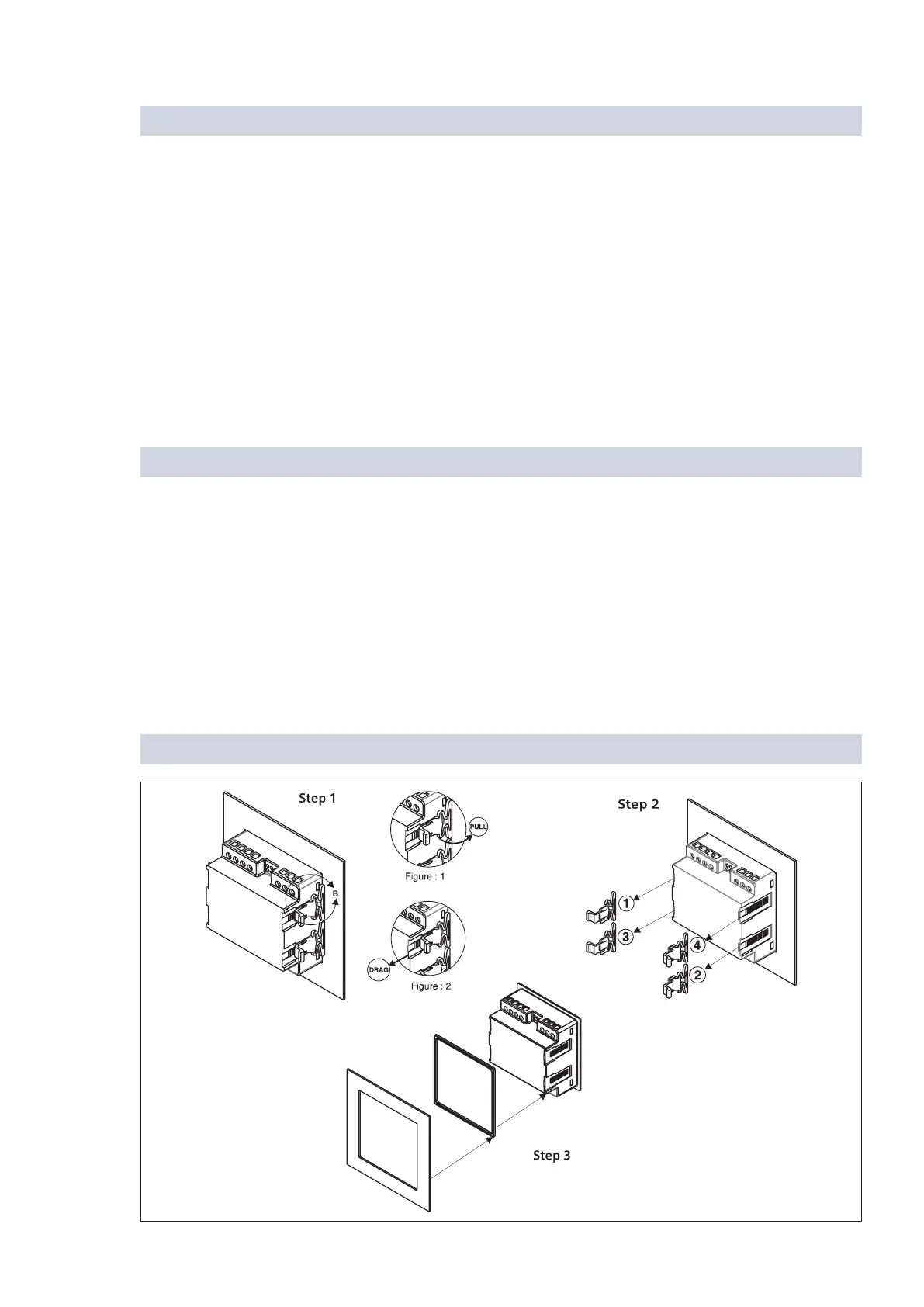
For demounting the meter