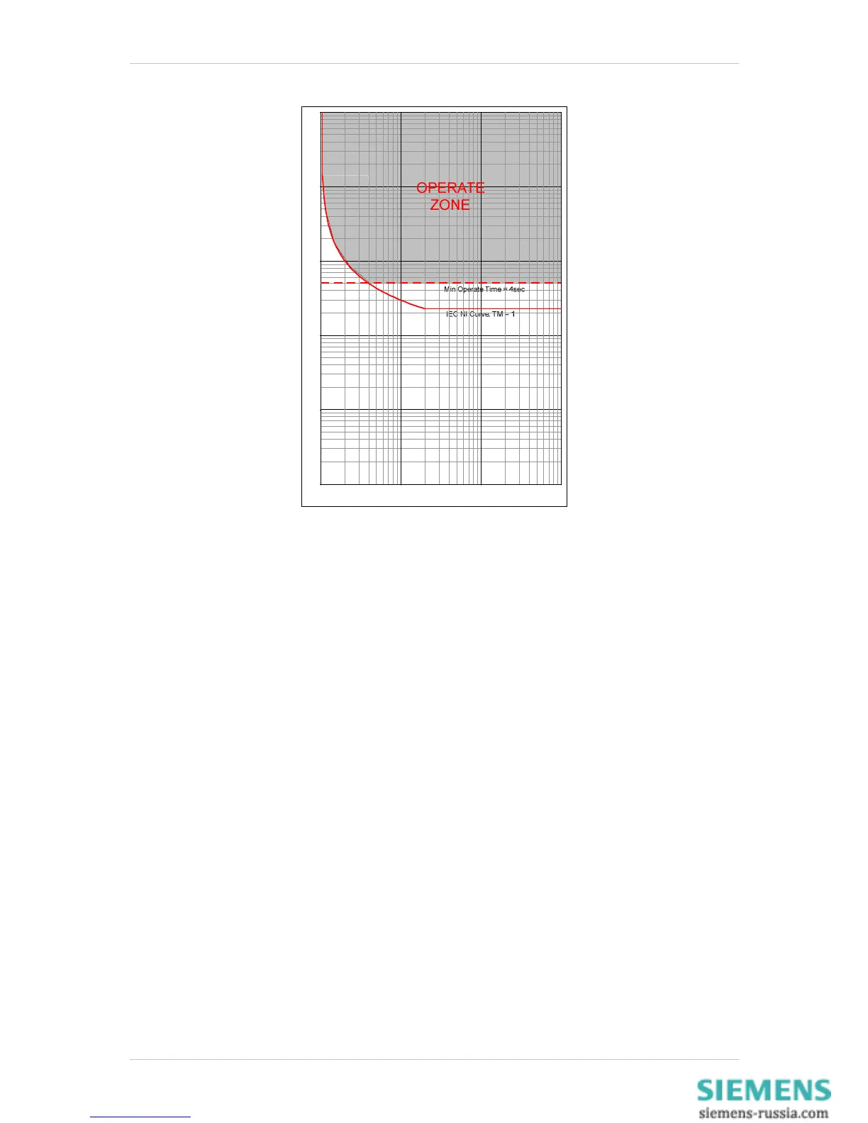
Figure 2.1-2 IEC NI Curve with Minimum Operate Time Setting Applied
To increase sensitivity, dedicated Earth fault elements are used. There should be little or no current flowing to
earth in a healthy system so such relays can be given far lower pick-up levels than relays which detect excess
current ( > load current) in each phase conductor. Such dedicated earth fault relays are important where the fault
path to earth is a high-resistance one (such as in highly arid areas) or where the system uses high values of
earthing resistor / reactance and the fault current detected in the phase conductors will be limited.
2.1.1 Selection of Overcurrent Characteristics
Each pole has two independent over-current characteristics. Where required the two curves can be used:
To produce a composite curve
To provide a two stage tripping scheme
Where one curve is to be directionalised in the forward direction the other in the reverse direction.
The characteristic curve shape is selected to be the same type as the other relays on the same circuit or to grade
with items of plant e.g. fuses or earthing resistors.
The application of IDMTL characteristic is summarised in the following table:
Page 12 of 40 ©2011 Siemens Protection Devices Limited

 Loading...


