2
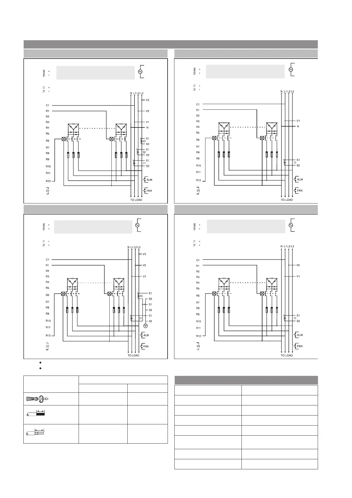
Terminal connections
NOTE :
ForN/W selection 2P2W voltage(V)appliedbetween V1 &V2and connect CT forI1[Do notuse V3, N, I2 &I3terminal ]
LL
ForN/W selection 1P2W voltage(V)appliedbetween V1 &Nand connect CT forI1[Do notuse V2, V3, I2 &I3terminal ]
LN
3 Phase -3Wire
2 Phase -2Wire
1 Phase -2Wire
3 Phase -4Wire
Where,
T1 &T2-Thermistor Input
Where,
T1 &T2-Thermistor Input
Where,
T1 &T2-Thermistor Input
Where,
T1 &T2-Thermistor Input
Wiring Diagram
Control Supply
Control Supply
Control Supply
Control Supply
K1
K1
K12
K12
K1
K1
K12
K12
Serial Communication
Interface standard and protocol
Communication address
Transmission Mode
Data types
Transmission distance
Transmission speed
Parity
Stop bits
RS AND485 MODBUS RTU
1to 255
Half duplex
Float and Integer
500 Meter maximum
300, 600,1200, 2400, 4800, 9600,
19200 (in bps)
None, Odd, Even
1or2
7UG057..
L, N, V*, I*, R*, C, NO RS485, T1, T2
0.5 Nm 0.4 Nm
Solid
1 x (0.75 to 2.5) mm
2
2 x 0.5 to 2 x 1.5 mm
2
0.5 mm
2
Stranded with end sleeve
1 x (0.5 to 2.5) mm
2
2 x (0.5 to 1.5) mm
2
0.5 mm
2
Note: The distance between APFC and external Current transformer
should be kept as short as possible. Use shielded cable or twisted pair
cable between APFC and Current transformer for long distance (Greater
than 1m).
* Not applicable for 7UG0571-1FT20
* Not applicable for 7UG0571-1FT20
* Not applicable for 7UG0571-1FT20
* Not applicable for 7UG0571-1FT20

 Loading...


