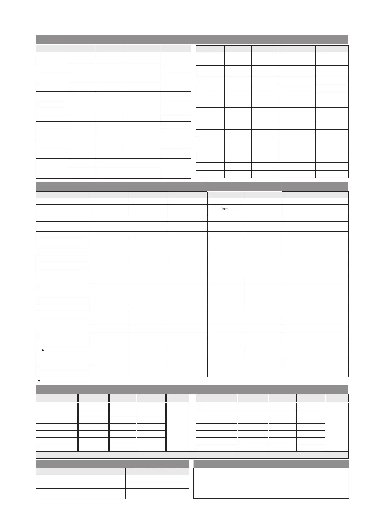
Level1
PASS WORD
CHNG PSWD
NETW SELN
NEWPSWD
LEVL
Display
Condition
Password
Change
Password
Network
Selection
New
Password
Level
Indication
Parameter
1000 (PW1) ;
2000 (PW2)
NO
3P4W
0
LEVL 1
Default Value
0000 – 9998
YES /NO
3P4W / 3P3W /
1P2W / 2P2W
0000 – 9998
–
Range
CT SEC
CT PRIM
PT SEC
PT PRIM
PHSE COMP
Only Valid for
1P2W & 2P2W
TH VOLT
NOM VOLT
CT Secondary
CT Primary
PT Secondary
PT Primary
Phase
Compensation Angle
Threshold
Voltage
Nominal
Voltage
Auto
Initialization
AUTO INIT
5A
5A
350V
350V
0
0%
For1P2W/3P4W-240V
For3P3W/2P2W-415V
YES
1A /5A
1A/5A-9999A
100V – 500V
100V to 500KV
0, 90, 120,
210, 240, 330
0–100%
50 – 440V
YES /NO
Display
Condition
Parameter
Default Value
Range
Relays Count
Control Mode
Target
PowerFactor
Step time
Discharge Time
(Reconnection
time)
Control
Sensitivity
settings
Slave ID
RLY CNT
CNTL MODE
TRGT PF
STEP TIME
DSHG TIME
SLVE ID
CNTL SENS
12
Auto
1.000
5S
180 S
1
60%
1– 12 /14
Auto /Manual
0.800 to -0.800
1Sto 999 S
1Sto 9999 S
001 – 255
55% to 100%
Parity
Baud Rate
Stop Bits
Backlight
Low Current
PAR-ITY
BAUD RATE
STOP BITS
BACK LGHT
Low Curr
NONE
9600
1
0
0
NONE / ODD /
EVEN
300/600/1200/
2400/4800 /
9600/19K2
1or2
0to 7200 Sec
0-50%
Level3accessible
onlywhen control
mode is manual
Switching
Program
SWNG PROG
Auto
Auto / Linear /
Rotational
Level2
Refer only if trip time setting is ON
else all tripping are instantaneous
Over Voltagesetting
Under Voltage
Under Voltage setting
Total HarmonicDistortion
Over Compensate
Under Compensate
Step Error
Step ErrorSetting
STEP ERR
STEP ERR.S
CT Polarityerror
Hysteresisvoltage
HysteresisPF
Factory Default
Reset Energy Pass word
THD IRange
Reset Energy
Reset kWh
ResetkVAh
ResetkVArh
Over Temperature
SETO.VLT
UNDR VOLT
SETU.VLT
THDI ERR
OVER COMP
UNDR COMP
CT ERR
TEMP RNGE
THDI RNGE
FANSET
HYSVOLT
HYSPF
FACT DFLT
RSET ENGY
RSET ENGY
RSET kWh
RSETkVAh
RSETVArh
OVER TEMP
190V (L-N)
340 (L-L)
OFF
260V (L-N)
460 (L-L)
ON
OFF
ON
ON
20
ON
65 C
OFF
OFF
2
1
NO
NO
NO
NO
NO
2001
OFF
All capacitor banksare blocked
Disconnect Allsteps
(For NominalVoltage)
Prompted onlyifoverTEMPisoff
FANON
Only Valid if customer wants
to reset energy
5min
5min
Inst
5min
5min
NA
Inst
5min
2.5min
1min
Inst
1min
1min
NA
Inst
50 - 240V (L-N)
85 - 415 (L-L)
ON / OFF
50 - 277V (L-N)
85 - 480 (L-L)
ON / OFF
ON / OFF
ON / OFF
ON / OFF
20 to 80%
ON / OFF
0-100
ON / OFF
ON / OFF
1to 10%
1to5%
20 - 100% 50%
YES/NO
YES/NO
YES/NO
YES/NO
YES/NO
0001 – 9999
ON / OFF
Nameof Parameter
No Voltage Release
Trip time setting
TRIPTIME
Over Voltage
Nomenclature
Default Value
Range
NO VOLT
OVER VOLT ON
OFF
When any phaseismissing
Disconnect Allsteps
ON / OFF
ON / OFF
Activate Deactivate
Action to be take nbyAPFC
Fa nSetting
Over TemperatureSetting
Disconnect Allsteps
Forresetting energy parameters user will be prompted the password. This passwordwill be value whichwill be greater than thetechnical passwordby1.
Leve l3
Prompted
onlyif
mode is
setto
manual.
Name of Parameter
Default Value
Range
Condition
OFFON /OFF
Relay8
OFF
OFF
OFF
OFF
ON /OFF
ON /OFF
ON /OFF
ON /OFF
Nomenclature
RLY8
RLY9
RLY10
RLY11
RLY12
RLY13
RLY14
OFF
OFF
ON /OFF
ON /OFF
Relay14
**
Relay12
Relay11
Relay10
Relay9
Relay13
**
Prompted
onlyif
mode is
setto
manual.
Nameof Parameter
Default Value
Range
Condition
OFFON /OFF
OFF
OFF
OFF
OFF
ON /OFF
ON /OFF
ON /OFF
ON /OFF
Nomenclature
OFF
OFF
ON /OFF
ON /OFF
Relay4
Relay5
Relay6
Relay7
Relay1
Relay2
Relay3
RLY4
RLY5
RLY6
RLY7
RLY1
RLY2
RLY3
**
13 & 14threlaywill be used for control switching onlywhen customer selects 14 relayin config. else forFAN&ALM respectively.
FanSettings
Setting
Description
None
FixedOn
Fan output permanentlyoff.
Fan output permanently on.
Fan output will turn on when the
temperatureexceed user setvalue.
Temperature ON/OFF (Setting range=0C- 100 C)
oo
NOTE:
2.5min
35 msec
90 sec
• A.INTwill be updateto'NO' automaticallyinconfigureafter auto initialization completion.
Reauto-Initialization will be done by onlychangingA.INT -Yes in configure manually.
If DI is high controller work in manual mode&if Lowreturnto'Auto' mode.
Recommended that number of relays nottobechanged during normaloperation If done so,
restartthe unit.
•
•
•
• Recommended to restartthe unit if Switching program(SWP) is changed duringnormaloperation
forproperfunctionalityinaccordance with thechosen control mode.

 Loading...


