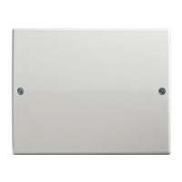
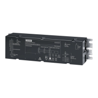
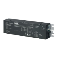
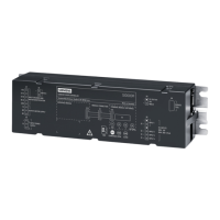
ACC-AP Controller Diagram
5.2.1 Description of Numbered Items in the Diagram
Power supply input – Vin, 12-24V DC
Power out with Vin voltage
(direct connection to Vin to allow daisy chaining of power to another devices)
Relay output 1. Potential free NC-COM-NO. Bistable function. Max 30V DC, 2A
Relay output 2. Potential free NC-COM-NO. Monostable function. Max 30V DC,
2A
General input 1 & 2 plus 3 & 4. Software defined.
For instance, closing contact or monitored input.
Open-collector output 1 & 2 plus 3 & 4. Software defined.
Wiegand Reader 1 and 2 bus connection plus power.
Max 700mA (Vin) or 200mA (12V) in total for both outputs.
RS485 Communications Bus. See also 22.
Micro-SD card slot. Note that no card is supplied. Used for system restore /
update.
Battery socket. Type CR2032.
Note that the supplied battery should be mounted with the plus (+) downwards.
USB-A Full-speed –
future use
.
USB-A Hi-speed –
future use
.
Ethernet port RJ45 (Network)
Opening tamper switch. Protects for opening the lid.
USB-B connection to computer for setup.
Jumper – EOL Reader 1 & 2. End of line resistor for reader 1 & 2.
Default
–
ON
.
Jumpers – EOL communications 1 & 2. End of line resistor.
Default
–
ON
.
Jumper – Power reader 1 & 2. Voltage output for reader, Vin or 12V DC.
Default
–
Vin
.
Factory settings. Reset the unit to delivery status by pressing with a non-metal
stick for at least five seconds.
Removal tamper. Screw MUST be mounted to fulfill the tamper feature.
LED indicator.
● Red: Controller is starting up
● Orange: Application running
● Green: Application running, connected with SiPass integrated
● Off (Dark): Application not running. (This can occur during a Firmware
upgrade.)

 Loading...


