Do you have a question about the Siemens SIDOOR ATD401W and is the answer not in the manual?
Explains what SIDOOR is, its purpose and benefits for industrial applications.
Details the contents, target audience, firmware versions, and figures used in the manual.
Outlines available SIDOOR system manuals and quick start instructions for users.
Details various Siemens support channels, including online resources, technical support, and training.
Covers crucial details regarding product usage and intended applications.
Provides essential safety guidelines for working with electrical devices, including handling hazards and precautions.
Details how to prevent damage to equipment from electric fields or electrostatic discharge (ESD).
Discusses industrial security functions, cyber threats, and customer responsibilities for secure operation.
Outlines residual risks associated with power drive systems, including unintentional movements and environmental factors.
Illustrates the general system configuration for automatic door control with SIDOOR, including components and application areas.
Details the different product categories within the SIDOOR system, including controllers, geared motors, and power supplies.
Lists optional units like SERVICE TOOL, LINK adapter, and SOFTWARE KIT for system implementation and maintenance.
Introduces the section describing SIDOOR control unit functions, categorized into basic, system, extended, and safety functions.
Presents a table detailing available SIDOOR functions and their compatibility with different control units (ATD401W, ATD420W/ATD430W).
Covers essential functions required for operating a SIDOOR door controller, including learn run and drive orders.
Covers system functions that enable better monitoring and diagnostics of the SIDOOR system.
Covers advanced features for implementing application-specific requirements, such as ImpulseDrive and AssistedDrive.
Introduces safety functions that expand the system with optional devices and secure input signals.
Details optional safety devices that can be connected to the system, such as light barriers and ESPE.
Covers the safety package of SIDOOR controllers, fulfilling DIN EN ISO 13849-1 requirements.
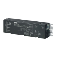
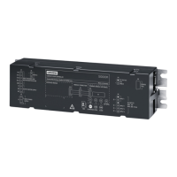
Provides an overview of the SIDOOR ATD4xxW controller, including its components and general information.
Outlines requirements for the installation site and the procedure for mounting the controller and standard rail mounting.
Provides terminal information and wiring rules for SIDOOR ATD4xxW, detailing conductor assignments and stripping insulation.
Explains signal assignments for drive functions at inputs X5 and X6, depending on the control unit and configuration.
Provides an overview and task description for the relay module, detailing door states reported to the higher-level controller.
Details the PROFIBUS module, including GSD files, LED signals, DIP switches, and wiring.
Covers the PROFINET module, including its overview, task, LED signals, network topologies, and GSD files.
Explains local/master operation and how the slave signals the master to assume control via StatW1.
Describes master monitoring of the internal communication channel to the PLC, ensuring defined responses to various situations.
Provides essential safety information and an overview of the commissioning process, including electrical and mechanical hazards.
Details the preparation steps for connecting and installing the control unit, including nudging the door and opening the cover.
Explains the procedure for connecting the geared motor to the SIDOOR ATD4xxW control unit, including cable and connector details.
Guides on connecting the power supply and performing the learn run, including notes on fuses and output transmission.
Details how to connect digital input signals to terminals X6, X5, and X4, and select FBLOCK configuration.
Provides procedures for commissioning the control unit on PROFIBUS DP and PROFINET IO with a higher-level controller.
Covers final settings for relay modules and sensors, and performs checks on permissible energies and forces.
Explains how operating states are indicated on the 7-segment or digital display and retrieved via status words.
Details fault management, including automatic acknowledgment options for ATD401W and response procedures for ATD420W/ATD430W.
Outlines recommended maintenance cycles for the SIDOOR system components, including geared motors and control units.
Provides guidance on environmentally friendly recycling and disposal of old devices, recommending certified disposal companies.
Explains the user data block structure in telegrams for PROFIBUS/PROFINET, covering parameter and process data areas.
Defines the PROFIBUS 'variable-speed drives' profile for accessing parameters in the slave.
Explains process data transfer via telegrams, covering receive and send words, and telegram type.
Provides parameter and setting ranges for various SIDOOR motors and profiles.
Provides a template for recording controller, motor, power supply, and software/additional device configurations.
Lists relevant standards and directives for safety, EMC, communications, and application-specific requirements.
Details standards for electrosensitive and pressure-sensitive protective equipment, and two-hand control devices.
Provides a comprehensive list of abbreviations and their explanations used throughout the manual.
| Supply voltage | 24 V DC |
|---|---|
| Mounting | Wall mounting |
| Relative humidity | Max. 95%, non-condensing |
| Housing material | Plastic |
| Product type | Automatic Door Control System |
| Communication | RS485 |


