Siemens Building Technologies CM2N3204E / 1.1999
Landis & Staefa Division 9/20
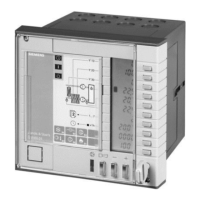
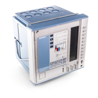
The controller consists of controller insert and base.
The controller insert accommodates all operating elements and the electronic circuits. It
is secured to the base by two screws which are designed such that they push the insert
away from the base when loosened.
An EEPROM stores all setting values. In the event of a power failure, the setting values
are thus retained for an unlimited period of time. The reserve for the weekly time switch
(typically 48 hours) is contained in the controller insert. For this reason, the insert can be
removed from its base without affecting the actual time settings.
The base is made of plastic and is designed for both wall and flush panel mounting. In
the case of flush panel mounting, the controller is secured by a clamp. The base carries
four terminal blocks and a terminal strip for establishing the electrical connections with
the controller insert.
The RWI65.02 is operated from four operating levels: information level, setting level,
time switch program level, and commissioning level.
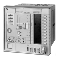
When the front door is closed, the display window displays the following information:
selection of operation (black pointer), manipulated variables, temperatures, weekday,
time, and status information.
The following settings can be made (if not disabled): operating mode (Automatic, fan
speed II, fan speed I, Standby), time of day, weekday, and summer- or wintertime.
Y 20
Y 10
Y 30
T
T
T
1 ... 7
+ 1h
E6E4
E1
E2
E5
B9
E3
∆p
!
2
I,II
I,II
I,II
AEROGYR RWI65.02
100
0
100
19.5
17.5
12.4
1
22.45
A0b0
120
TM
1
2
3
4
5
6
7
8
13131211109
3204Z02
1
2
3
4
5
6
7
8
9
10
1 Button for automatic plant operation ( )
2 Button for plant operation using fan speed II
3 Button for plant operation using fan speed I
4 Button for Standby mode (incl. frost protection)
5 Black pointer, indicates plant operation selected with the manual switch (buttons 1 to 4)
6 Button for setting the current weekday (Mo = 1 .... Su = 7)
7 Button for setting the actual time
8 Black pointer, indicates that the clock is set to summertime (no indication = wintertime)
9 Operating card 1 (for operating level 1)
10 LED (green) for indication of the plant’s operational status (fans ON = LED lit, OFF = dark)
11 Universal button with LED (red) for indication, acknowledgement and resetting of fault statuses
12 Buttons for adjustments
13 Key hole for opening the front door (key enclosed)
Mechanical design
Operation
Information level
(operating level 1)
Front door closed
Legend
 Loading...
