Instruction manual AQ101, AQ101D, AQ110P, AQ01 10 (48)
Always ensure that current measurement circuits are not energized
during disconnection.
See rated voltages and connector tightening torques from chapter 7.1
“Technical data”.
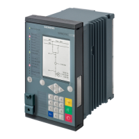
1.2.2 AQ101, AQ101D ARC FLASH PROTECTION RELAYS
Binary input 2 – Negative
Binary input 1 – Negative
Binary input 2 – Positive
Binary input 1 – Positive
Binary output 1 - +24V output
Binary output 1 – GND output
Sensor Channel 1 - Supply
Sensor Channel 1 – Signal
Sensor Channel 1 – Grounding
Sensor Channel 2 - Supply
Sensor Channel 2 – Signal
Sensor Channel 2 – Grounding
Sensor Channel 3 - Supply
Self-supervision contact – normal
state
Sensor Channel 3 – Signal
Self-supervision contact – failure
state
Sensor Channel 3 and 4 – Grounding
Self-supervision contact – common
Sensor Channel 4 - Supply
Sensor Channel 4 – Signal
Sensor 5 – Transmitter **
*) Trip contact T3 may be normally open or normally closed type. Refer to the ordering codes.
**) Sensor 5 is optional for fiber sensor. Refer to the ordering codes.
See rated voltages and connector tightening torques from chapter 7.1
“Technical data”.
 Loading...