Instruction manual AQ101, AQ101D, AQ110P, AQ01 33 (48)
7 TECHNICAL DATA
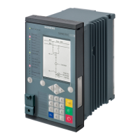
7.1 AQ101, AQ101D, AQ110P ARC FLASH PROTECTION RELAYS
7.1.1 MOUNTING AND INSTALLATION
Panel material:
Panel thickness (min-max):
Metal panel
1.0 – 5 mm / 1/16” – 13/64”
Panel mounting screw type:
Key size:
Tightening torque (min-max):
ISO 14581-M4x12 galvanized
Torx T20
1.5 – 2.0 Nm / 13 – 18 in-lbs
Grounding nut type:
Key size:
Tightening torque (min-max):
DIN934-M5 galvanized
8
2.5 – 3.0 Nm / 22 – 26 in-lbs
Connectors X1 and X2 type:
Wire cross section (solid and multicore) (min-max):
Minimum stripping length:
Screw tightening torque (min-max):
Phoenix contact MSTB 2,5/15-ST-5,08
0.2 – 2.5 mm2 / 24-12 AWG
7 mm / 0.275“
0.5 – 0.6 Nm / 4.4 – 5.3 in-lbs
Connector X3 (AQ110P only)
Wire cross section (solid and multicore) (min-max):
Minimum stripping length:
Screw tightening torque (min-max):
0.5 – 6.0 mm2 / 20 – 10 AWG
14 mm / 0.55”
0.5 – 0.6 Nm / 4.4 – 5.3 in-lbs
Fiber connectors
Nut tightening torque:
Tripping time using HSO (AQ110P only):
Tripping time using mechanical relays (T1-T4):
Reset time
Light activation:
Overcurrent measurement (AQ110P only):
Protection stages active after energization:
*) Total trip time using arc light (L>) or phase/residual overcurrent (I>) and arc light (L>)
 Loading...