Instruction manual AQ101, AQ101D, AQ110P, AQ01 16 (48)
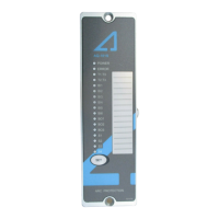
2.2 POTENTIOMETERS (AQ110P ONLY)
Current pick-up setting (set point) is done with potentiometers on the back side of
the device. Use flat head screw driver for moving the potentiometer to the desired
set point. See chapter 4.1.2 for accurate setting of the current activation level.
Figure 2-1: Current pick-up potentiometers.
2.3 SIEMENS PROTECTION SCHEME LOGICS (AQ101, AQ101D, AQ110P)
Following tables describes the basic functionality of scheme 0 (AQ101, AQ101D),
scheme 1a, 1b and 2a (AQ110P).
Following tables doesn’t segregate the light and light + current mode trip settings.
In case light and current mode has been chosen with dip switches, corresponding
sensor activation requires simultaneous overcurrent injection. For the CBFP
operation, refer to the relevant dipswitch settings.
Activation table letters:
X = activation of output when signal is active
C = output activates according to the CBFP functionality
Y = output activation has more than one function depending on the
setting of CBFP function. See dip switch settings on chapter 2.1.
For C and Y activation, refer to the scheme logic tables
Table 2-5 and Table 2-6.
 Loading...