EasyManua.ls Logo

Siemens Arcteq AQ101 - Aq101, Aq101 D; Aq110 P

Siemens Arcteq AQ101
48 pages
To Next Page IconTo Next Page
To Previous Page IconTo Previous Page
Loading...
Instruction manual AQ101, AQ101D, AQ110P, AQ01 17 (48)
2.3.1 AQ101, AQ101D
Scheme 0
T1
T2
T3***
T4***
BO1
S1
X
X
X
S2
X
X
X
X
S3
X
X
X
X
S4
X
X
X
X
X
S5**
BI1*
BI2
X
X
Table 2-5: AQ101 scheme 0 protection scheme logics.
*) BI1 is common over current measurement channel. BI1 is necessary to be activated
simultaneously with light sensors for making trip with light + current settings. Refer to DIP switch
configuration.
**) S5 is optional and may be used as fiber optic sensor input (AQ101 and AQ101D). Refer to the
technical manual and ordering codes.
***) T3 and T4 are mainly for fault location identification.
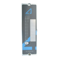
2.3.2 AQ110P
Scheme 1a
Scheme 1b
T1
T2***
T3**
T4**
BO1
HSO1
HSO2
QD
T1
T2***
T3**
T4**
BO1
HSO1
HSO2
QD
S1
X
X
X
X
X
X
X
X
X
X
S2
X
Y
X
X
X
X
X
Y
X
X
X
X
S3
X
Y
X
X
X
X
X
Y
X
X
X
X
S4
X
Y
X
X
X
X
X
X
Y
X
X
X
X
X
S5*
X
Y
X
X
X
Y
X
X
BI1
X
Y
X
X
X
Y
X
X
BI2
X
Y
X
X
X
X
Y
X
X
X
IL1-3
X
X
Io
X
X
Table 2-6: AQ110 scheme 1a and 1b protection scheme logics.

Table of Contents

Related product manuals