EasyManua.ls Logo

Siemens Arcteq AQ101 - Page 21

Siemens Arcteq AQ101
48 pages
To Next Page IconTo Next Page
To Previous Page IconTo Previous Page
Loading...
Instruction manual AQ101, AQ101D, AQ110P, AQ01 21 (48)
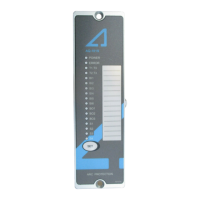
LED
Color
OFF
Steady ON
Blinking
Arcteq logo
Blue
Auxiliary supply
disconnected
Auxiliary power
connected
N/A
Power
Blue
Auxiliary supply
disconnected
Auxiliary power
connected
N/A
Error
Red
System healthy
System failure
Configuration
mismatch. Protection
partly operational.
T1 / T2 / T3 /
T4
Red
Normal status
Corresponding trip
relay activated
N/A
S1
Amber
Normal status
Corresponding
sensor channel
activated.
Corresponding sensor
channel have loose
connection or system
set-up not performed.
S2 / S3 / S4
Amber
Normal status
Corresponding
sensor channel
activated.
Corresponding sensor
channel have loose
connection or system
set-up not performed;
S5 (AQ110P)
Amber
Normal status
Corresponding
sensor or quenching
device channel
activated.
Corresponding sensor
channel have loose
connection or system
set-up not performed;
BI1 / BI2
Amber
Normal status
Corresponding
binary input
activated
Corresponding binary
input have loose
connection
BO1
Amber
Normal status
Binary Output
activated
N/A
IL1 / IL2 / IL3
Amber
Normal status,
measured current
below set point
Corresponding
current channel
above set point.
Overcurrent stage
activated.
Unbalance alarm,
corresponding channel
CT connection is open,
corresponding channel
activated for over 10s
Io
Amber
Normal status,
measured current
below set point
Residual current
above set point.
Overcurrent stage
activated.
N/A
HSO1 /
HSO 2
Red
Normal status
HSO channel
activated.
N/A
Table 3-2: AQ110P LED indications definition.

Table of Contents

Related product manuals