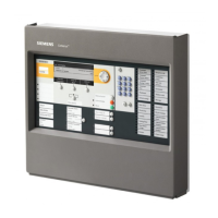
PXL Conventional Fire Alarm Control Panel
Installation
32
Wiring to the PCM-1
Refer to Table 8 and the Connection Diagram. Dress the field wiring
that will be going to the PCM-1 terminals. Strip the insulation from the
wiring and connect the wires to the appropriate screw terminals.
TABLE 8
WIRING TO THE PCM-1
Screw Terminal Application
TB1, 1-4 2 Initiating Device Circuits
TB2, 1-4 2 Initiating Device Circuits
TB3, 1-4 2 Initiating Device Circuits
TB4, 1-4 2 Initiating Device Circuits
TB5, 1-4 2 Initiating Device Circuits
TB6, 1-4 2 Initiating Device Circuits
Wiring to the Optional PZE-4B Modules
Refer to Table 9. Dress the field wiring that will be going to the
PZE-4B terminals. Strip the insulation from the wiring and connect
the wires to the appropriate screw terminals.
TABLE 9
WIRING TO THE PZE-4B
Screw Terminal Application
TB1, 1-4 2 Initiating Device Circuits
TB2, 1-4 2 Initiating Device Circuits
Wiring to the PPS-10M
Refer to Table 10. Dress the field wiring that will be going to the
PPS-10M terminals. Strip the insulation from the wiring and connect
the wires to the appropriate screw terminals.
TABLE 10
WIRING TO THE PPS-10M
Screw Terminal Application
TB1, XFR R/Y Transformer
TB1, XFR RED Transformer
TB1, XFR RED Transformer
TB1, AC PRM Main Power/Trans Power
TB1, AC PRM Main Power/Trans Power
TB1, ERG Earth Ground
Technical Manuals Online! - http://www.tech-man.com

 Loading...


