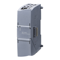
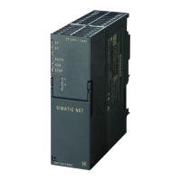
Displays and connectors
2.2 LEDs
CM 1243-5
Operating Instructions, 04/2011, C79000-G8976-C246-01
13
Display of the operating and communication status
The LED symbols in the following tables have the following significance:
Table 2- 3 Meaning of the LED symbols
Symbol
-
LED status OFF ON (steady light) Flashing, one color Flashing
yellow-green
Not relevant
The LEDs indicate the operating and communications status of the module according to the
following scheme:
Table 2- 4 Display of the basic states of the module by the "DIAG" LED
DIAG
(red / green)
Meaning Comment
Power OFF
green
RUN without errors
flashing green
Startup
STOP without errors
No project data
Firmware update
The individual states are signaled by the
RUN/STOP and ERROR LEDs (see below).
flashing red
Problem / error The individual states are signaled by the
RUN/STOP and ERROR LEDs (see below).

 Loading...


