Installing, connecting up and commissioning
3.3 Pin assignment of the socket for the external power supply
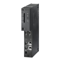
CM 1243-5
22 Operating Instructions, 04/2011, C79000-G8976-C246-01
Table 3- 2 Procedure for installation and connecting up
Step Execution Notes and explanations
1 Mount the CM on the DIN rail and connect it to
the module to its right.
Use a 35 mm DIN rail.
The slots to the left of the CPU are permitted.
2 Secure the DIN rail.
3 Secure the power supply wires to the power
output of the CPU.
4 Secure the wires of the power supply to the
plug supplied with the CM and insert the plug
in the socket on the top of the CM.
The pinning is shown beside the socket on the top of the
housing. You will also find this in the section Pin assignment of
the socket for the external power supply (Page 22).
5 Connect the PROFIBUS cable to the D-sub
female connector of the CM.
Lower surface of the CM
6 Turn on the power supply.
7 Close the front covers of the module and keep
them closed during operation.
8 The remaining steps in commissioning involve
downloading the STEP 7 project data.
The STEP 7 project data of the CM is transferred when you
download to the station. To load the station, connect the
engineering station on which the project data is located to the
Ethernet interface of the CPU.
You will find more detailed information on loading in the
following sections of the STEP 7 online help:
"Loading project data"
"Using online and diagnostics functions"
3.3 Pin assignment of the socket for the external power supply
/
0
1(&
&/$66
'&9$
Figure 3-2 Socket for the external 24 VDC power supply (view from above)
 Loading...