Installation and connecting up
3.2 Installing the CP
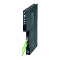
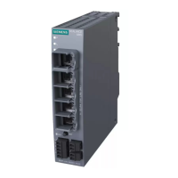
CP 1542SP-1, CP 1542SP-1 IRC, CP 1543SP-1
Operating Instructions, 01/2017, C79000-G8976-C426-03
33
Installation location - Dependency of the temperature range
The module must be installed so that its upper and lower ventilation slits are not covered,
allowing adequate ventilation. Above and below the modules, there must be a clearance of
25 mm to allow air to circulate and prevent overheating.
Note the dependency of the permitted temperature range of the installation location.
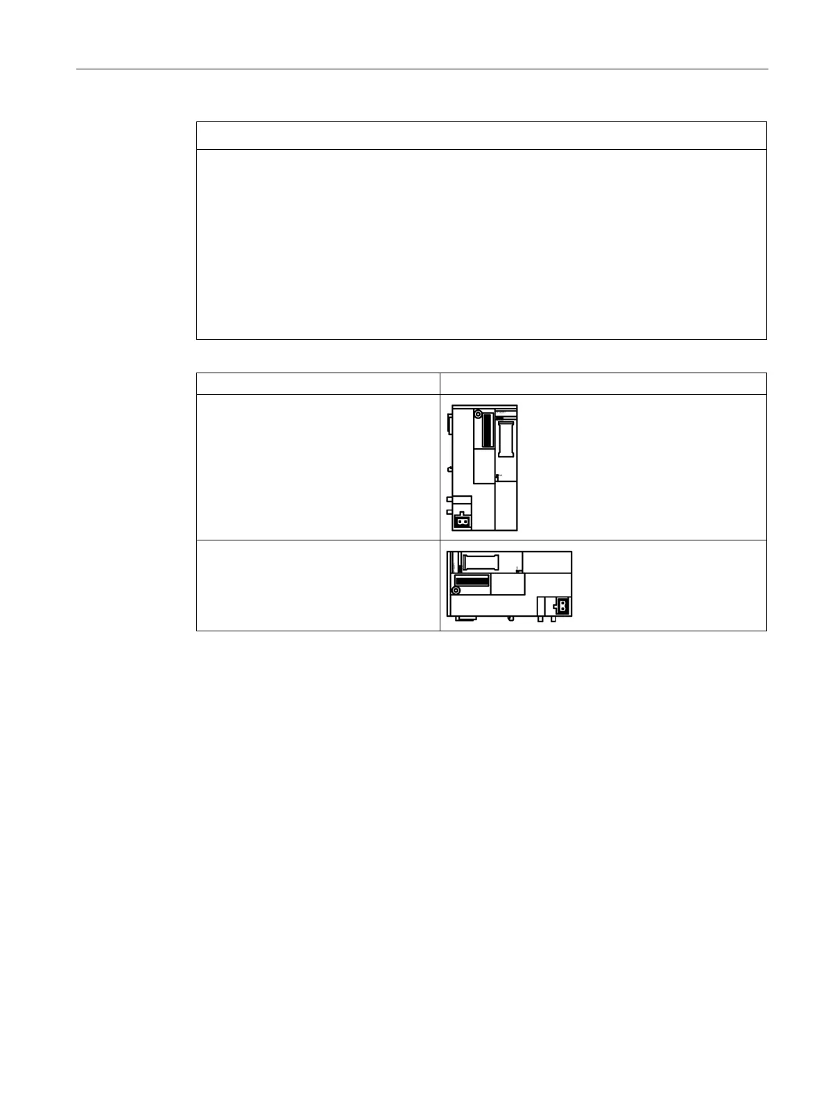
• Horizontal installation of the rack (DIN rail) means vertical position of the CP.
• Vertical installation of the rack (DIN rail) means horizontal position of the CP.
You will find the permitted temperature ranges in the section Technical specifications
(Page 109).
Installation position of the CP
Horizontal installation of the rack
Vertical installation of the rack
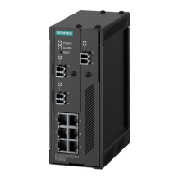
The CPU always occupies slot 1. In an ET 200SP you can plug in up to three of the following
modules in slots 1 ... 4 (see figure) to the right of the CPU:
● CMs
● CPs
● BusAdapter Send
Of these three modules, up to two CP 154xSP-1 modules can be plugged in. These two CPs
can be of the same type or different.
 Loading...