Installation, connecting up, commissioning
3.2 Procedure for installation and commissioning
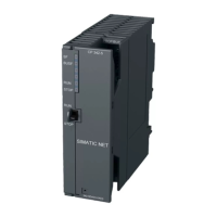
CP 342-5 / CP 342-5 FO
Manual, 07/2017, C79000-G8976-C146-10
35
Take measures to prevent transient voltage surges of more than 40% of the rated voltage.
This is the case if you only operate devices with SELV (safety extra-low voltage).
Notes on use in hazardous areas according to UL HazLoc
You may only connect or disconnect cables carrying electricity when the power supply is
switched off or when the device is in an area without inflammable gas concentrations.
This equipment is suitable for use in Class I, Division 2, Groups A, B, C and D or non-
hazardous locations only.
This equipment is suitable for use in Class I, Zone 2, Group IIC or non-hazardous locations
only.
Procedure for installation and commissioning
What to do / steps
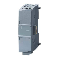
1. Install the CP on the S7 standard rail.
Slots 4 to 11 are permitted for the CP in racks 0 to 3 (connected by IM 360/361).
2. Establish the connection via the enclosed bus connector to the backplane bus.
Proceed as described in the sections dealing with installation and wiring, explained in
detail in /2/ (Page 48).
Note
No operation in the expansion rack with connection via an IM 365
The CP cannot be used in an expansion rack that is connected via the IM 365! Reason:
The required communication bus is not connected to the extension rack via the IM 365.
 Loading...
