Technical Specifications
27
CP 5611 Installation Instructions/Product Information
A5E00102070–01
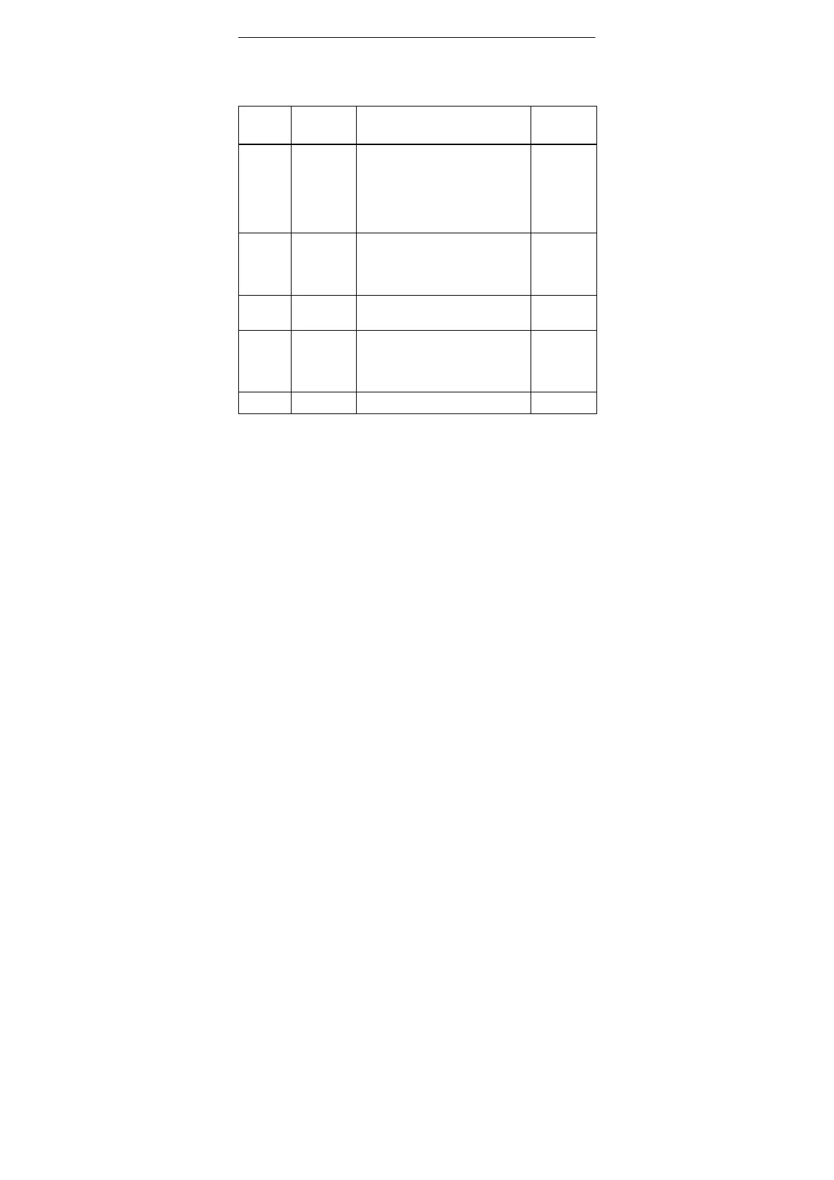
Tabelle 6-2 , continued
Pin No. Input/
Output
MeaningAbbrevia–
tion
6 P5EXT P5EXT supply (+5 V) of the 5V
supply. The current load caused
by an external consumer connec-
ted between P5EXT and M5EXT
must not exceed a maximum of
90 mA (short–circuit proof).
–
7 NC (P24V) Pin 7 is not connected With other
MPI/DP components, the P24V
pin of the 24 V floating power
supply can be applied to this pin.
–
8 LTG_A Signal line A of the CP 5611 mo-
dule
Input/
output
9 RTS RTS output signal of the CP 5611
module. The control signal is ’1’
active when the device (PG or
PC) is sending.
Output
Shield On connector housing
 Loading...