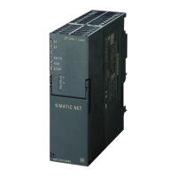
Do you have a question about the Siemens CU240S DP-F and is the answer not in the manual?
Lists available documentation types for SINAMICS G120 inverters and download links.
Explains the grading of safety notices (Danger, Warning, Caution, Notice) and their meanings.
Defines qualified personnel for setting up and operating the device according to safety standards.
Describes the functions and features covered for the CU240S, CU240S-DP, and CU240S DP-F.
Lists available optional accessories for SINAMICS G120 Control Units and Power Modules.
Details common, PM240, PM250, and commissioning features/functions of the CU240.
Shows the layout characteristics and block diagrams for CU240S variants.
Provides an overview of available interfaces like MMC, Option Port, Terminals, DIP switches, and connectors.
Lists factory settings for command and setpoint sources, BICO parameters, fixed frequencies, and faults.
Explains how to snap the Control Unit onto the Power Module and the 24 V power supply options.
Describes general terminal access, connector removal, and terminal wiring examples for CU240S.
Covers PROFIBUS DP interface, setting address via DIP switches, connecting to the network, cable lengths, and EMC precautions.
Details the RS485 interface, recommended connectors, bus termination, and equipotential bonding.
Provides general information on adapting the inverter via parameters using OP, STARTER, or MMC.
Explains parameter identification, types, notation, access levels, change states, data types, units, grouping, and active attributes.
Details factory default settings for command/setpoint sources, digital inputs/outputs, BICO parameters, and fixed frequencies.
Describes fitting the OP, function keys, changing parameters via OP, parameterization with MMC, and STARTER.
Explains how to parameterize the inverter by downloading parameter sets from MMC.
Covers connection possibilities for STARTER, project creation, and changing parameters online or offline.
Details quick commissioning, motor data identification, calculating motor/control data, commissioning application, series commissioning, and reset.
Explains inverter behavior based on commissioning settings, including start-up and parameter set operations.
Describes how to save parameter sets to PC, MMC, or OP and the manual/automatic download possibilities.
Covers normal start-up behavior with/without MMC, swap behavior, and automatic download faults.
Provides global and regional contact details for Siemens A&D technical support and online resources.
Explains how faults and alarms are displayed, reset methods, and message storage.
Details the meaning of various LEDs (SF, RDY, BF, ES, STO, SS1, SLS) for status display.
Shows status displays for SF, RDY, and BF LEDs based on different states.
Illustrates fail-safe function states (STO, SS1, SLS) indicated by specific LEDs.
Provides further LED indications for Safety commissioning and Parameter download from MMC.
Outlines diagnostic displays (LEDs, Alarm Numbers, Diagnostic parameters) and troubleshooting steps for PROFIBUS DP.
Guides on troubleshooting when the motor fails to start or when warnings/faults are displayed on the OP.
Introduces BICO technology for interconnecting internal/external signals, using binectors and connectors.
Explains Command Data Sets (CDS) and Drive Data Sets (DDS) for parameter grouping and switching.
Describes the quantity, parameter range, features, and description of digital inputs, including BICO parameterization.
Details the quantity, parameter range, features, and description of digital outputs and their common settings.
Covers quantity, parameter range, features, description, and example connections for analog inputs.
Outlines quantity, parameter range, features, description, and pre-set analog outputs.
Explains USS protocol, data structure, telegrams, PC connection, cable lengths, and timeouts.
Describes fixed frequency functionality, direct and binary-coded selection modes, and examples.
Details the Siemens standard, 2-wire, and 3-wire control methods, including redefined digital inputs and BICO connections.
Explains the MOP function for entering setpoints, its behavior, and modes of operation.
Describes the JOG function for checking motor/inverter functionality and positioning.
Covers PID controller features, structure, examples, and specific functions like dancer roll control.
Explains the setpoint channel for coupling setpoints and motor control, summation, ramp-function generator, OFF/braking functions, and manual/automatic operation.
Details the function blocks (AND, OR, XOR, NOT, D-FlipFlop, RS-FlipFlop, Timer, ADD, SUB, MUL, DIV, CMP) integrated in SINAMICS G120.
Covers electro-mechanical brakes, DC braking, compound braking, dynamic braking, and regenerative braking.
Explains the automatic restart function after power failures (line undervoltage, line failure) and its parameters.
Details the flying restart function, its behavior without/with speed encoder, and warnings.
Covers installation, change of control units, motor/brake dimensioning, regenerative load with SLS, and monitoring procedures.
Explains Vdc control for preventing DC link over/undervoltage, Vdc_max controller, and kinetic buffering.
Describes the positioning ramp down function for moving to a stop based on an external event.
Covers monitoring functions, messages, alarm numbers, identification of communications components, and standard diagnostics.
Details thermal motor protection concepts, temperature rise classes, thermal motor model, and motor temperature identification.
Explains general overload monitoring and power module thermal monitoring for power components.
Discusses V/f control, vector control (with/without encoder), speed controller, slip compensation, resonance damping, current limiting, and torque control.
Lists performance ratings for CU240S, including operating voltage, control methods, fixed/skip frequencies, and digital/analog I/O.
Provides technical data for the PROFIBUS DP interface, including LEDs, voltage supply, baud rates, and connections.
Lists accessories for the Control Unit, such as Operator Panel, PC Connection Kit, and Multi Media Card.
Explains electromagnetic compatibility requirements, self-certification, technical construction file, and EMC standards.
Defines EMC environments (First/Second) and categories (C1, C2, C3) according to EN 61800-3.
Details EMC emissions (Conducted & Radiated) and harmonic currents for SINAMICS G120 drives.
Lists relevant standards and directives like Low Voltage Directive, Machinery Directive, EMC Directive, UL, and ISO 9001.
Covers documentation, function tests for STO, SS1, SLS, and completing the acceptance log.
| Brand | Siemens |
|---|---|
| Model | CU240S DP-F |
| Category | Control Unit |
| Language | English |


