Functions
8.7 Communication via USS
Control Units CU240S
8-28 Operating Instructions, 11/2006, A5E00766042B AA
8.7.4 Parameter data channel (PKW)
Parameter data area (PKW)
The USS protocol defines for the inverters, the user data structure with which a master can
access the inverter slaves. The PKW (parameter identifier value) telegram section can be
used to monitor and/or change any parameter in the inverter.
PKW mechanism for processing parameters
Using the PKW mechanism parameters can be processed and monitored (write/read) as
described below. The parameter area includes at least 3 words and is set with parameter
P2013. Values for P2013 are the number of PKW words. Possible settings are 0, 3, 4, 127
with 127 for variable length.
3.(
,1'
3:(
3.:
VW
ZRUG
QG
ZRUG
UG
DQG
WK
ZRUG
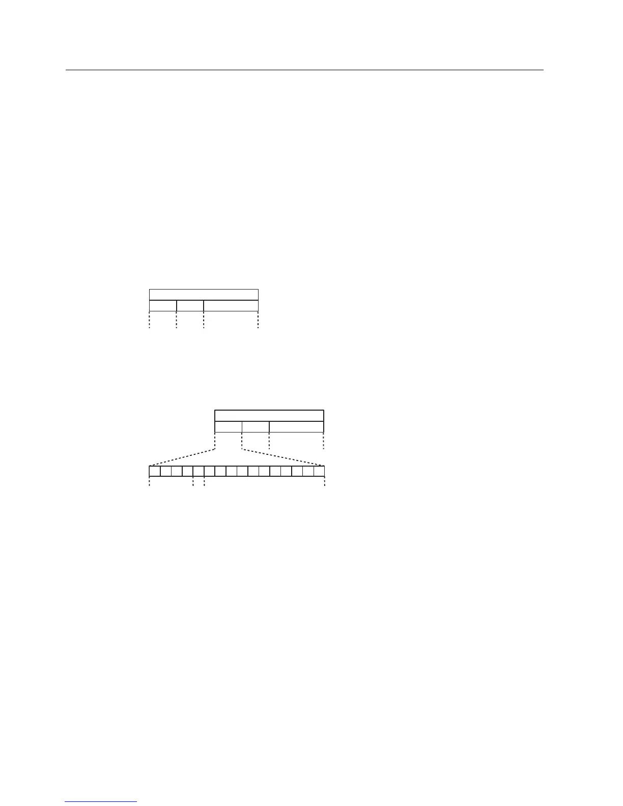
$EEUHYLDWLRQV 3.:3DUDPHWHULGHQWLILHUYDOXH
3.(3DUDPHWHULGHQWLILHU
,1',QGH[
3:(3DUDPHWHUYDOXH
Figure 8-20 Structure of parameter area (PKW)
Parameter identifier (PKE), 1
st
word
The parameter identifier (PKE) is always a 16-bit value.
3.(
,1'
3:(
3.:
$.
E318
630
VW
ZRUG
QG
ZRUG
UG
DQG
WK
ZRUG
Figure 8-21 PKE structure
● Bits 0 to 10 (bPNU) contain the remainder of the parameter number (value range 1 to
1999). For parameter numbers ≥ 2000 it is necessary to add an offset which is defined
with the high byte bits of IND.
● Bit 11 (SPM) is reserved and always = 0.
● Bits 12 to 15 (AK) contain the request or the response identifier.
 Loading...


