Functions
8.15 Brake functions
Control Units CU240S
8-82 Operating Instructions, 11/2006, A5E00766042B AA
8.15.2 Electronic brakes (only with PM240)
Overview
The SINAMICS G120 inverter has three electronic braking technologies:
● DC braking
● Compound braking
● Dynamic braking
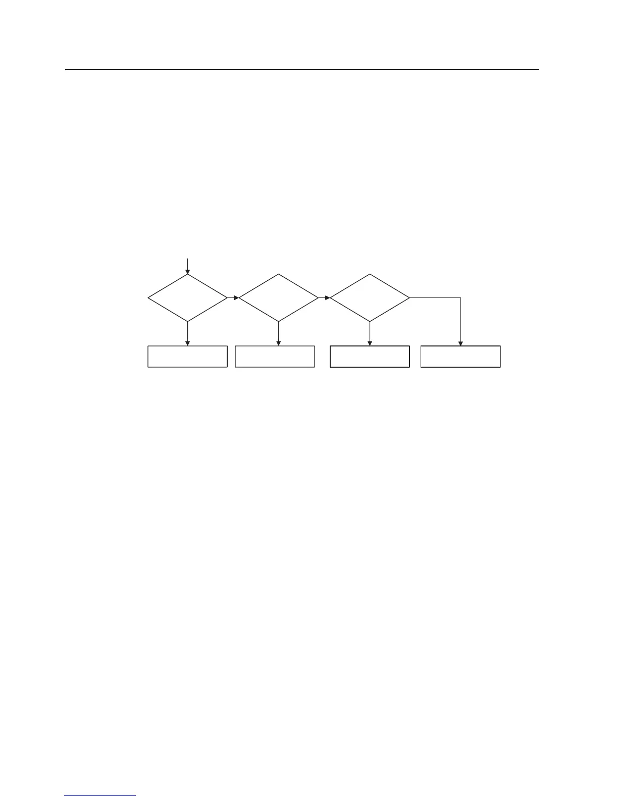
These brakes can actively brake the motor and avoid a possible DC link overvoltage
condition. The figure below shows the inter-dependency of the electronic braking functions.
'&EUDNLQJ
3!
"
'&EUDNLQJ
HQDEOHG
&RPSRXQGEUDNLQJ
HQDEOHG
'\QDPLFEUDNLQJ
HQDEOHG
'LVDEOHG
&RPSRXQG
EUDNLQJ
3!
"
'\QDPLF
EUDNLQJ
3!
"
QR QR QR
\HV \HV \HV
Figure 8-56 Inter-dependency of electronic brakes
8.15.2.1 DC braking
Data
P1230, P1233
P1232, P1234
Parameter range:
r0053 Bit00
Warnings: -
Faults: -
Function chart number: -
Description
The motor decelerates along a parameterized braking ramp if an OFF1 or OFF3 command is
output. A "flat" ramp must be selected so that the inverter is not tripped (shutdown) due to
the high regenerative energy which would cause a DC link overvoltage condition. The DC
brake should be activated while the OFF1 or OFF3 command is present if the motor is to be
braked faster. For DC braking, instead of continually reducing the output frequency/voltage
during the OFF1 or OFF3 phase, from a selectable frequency, a DC voltage/current is input
(refer to sequence 1).
The motor can be brought to a standstill in the shortest time using DC current braking (DC
brake). DC braking is selected as follows:
 Loading...


