Installing
3.2 Overview of the interfaces
CU240B-2 and CU240E-2 Control Units
Compact Operating Instructions, 01/2017, A5E39910322B AA
9
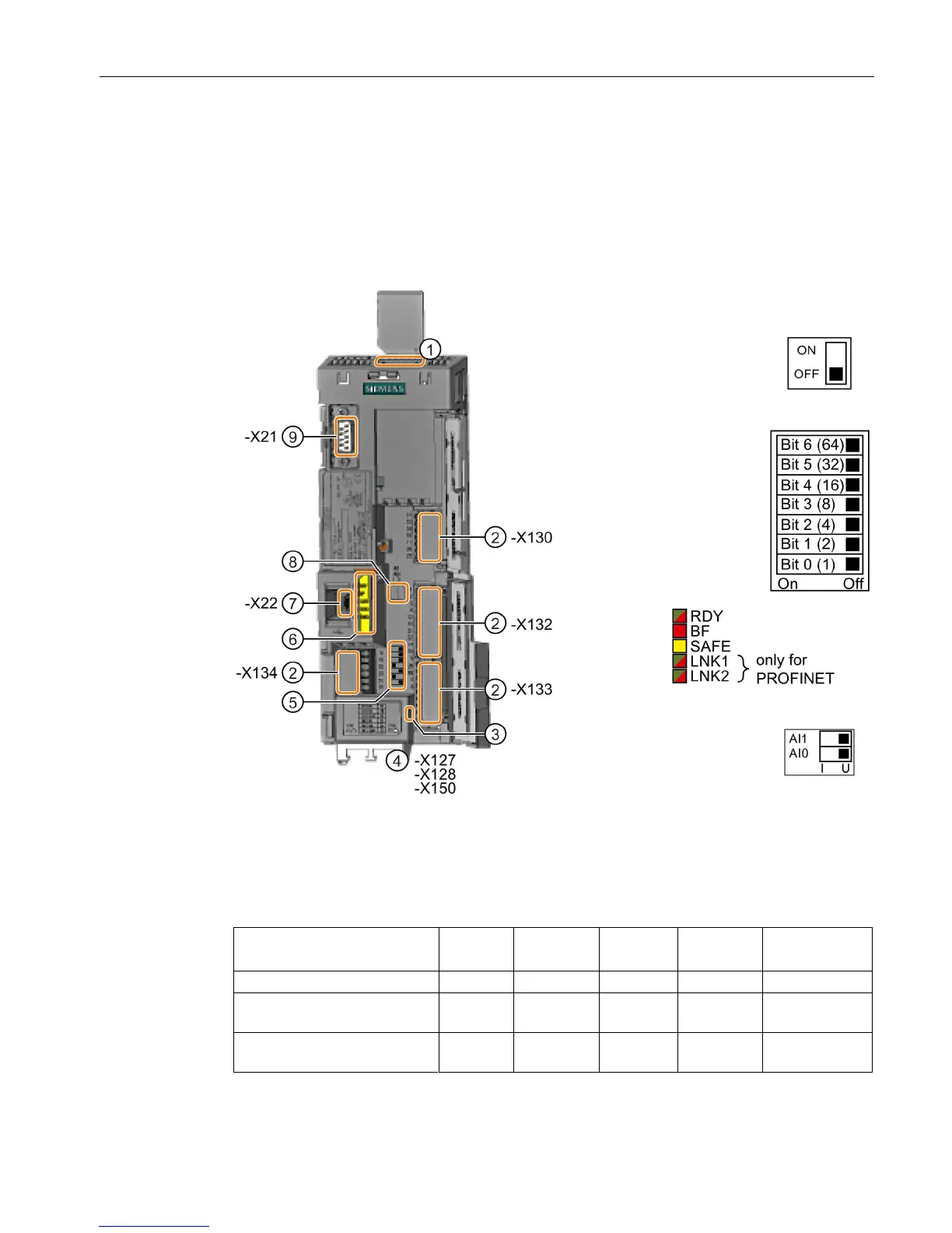
Overview of the interfaces
Interfaces at the front of the Control Unit
To access the interfaces at the front of the Control Unit, you must lift the Operator Panel (if
one is being used) and open the front doors.
Bus termination, only for
USS and Modbus field
buses
Fieldbus interface at the lower side
Selecting the fieldbus
address
On all Control Units with
the exception of
CU240E
USB interface for connection to a PC
Interface to the operator panel
1)
AI 1 is not available on the CU240B-2 Control Unit
Table 3- 1 Number of inputs and outputs
Fail-safe digital
inputs F-DI
1)
6 3 2 2 1
CU240E-2 F, CU240E-2 DP-F,
1)
Each fail-safe digital input F-DI used takes up two digital inputs DI